Drilling Machine Hold Down Clamp
Clamping items to the drill table should be a matter of course but I often can′t be bothered due to the time taken to assemble some form of clamp. Even if an item fit′s into the drill vice I rarely bother to fix the vice to the table. Fortunately I have been "bitten" only a couple of times, trying desperately to reach the stop button whilst avoiding rapidly rotating metal. This drill table hold down clamp should help to avoid laziness on my part.
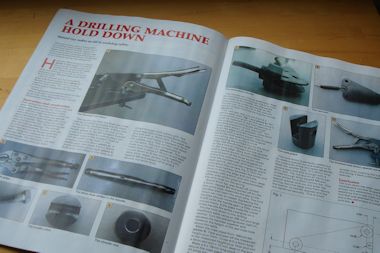
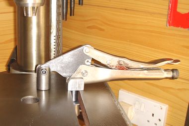
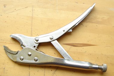
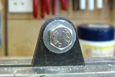
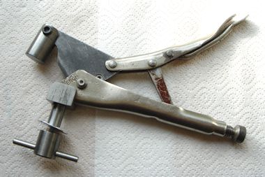
I definitely make no claims of originality for this project. I saw an article in Model Engineers′ Workshop (Issue 202, May 2013) (1) and thought I would make use of an old Mole wrench I had lying about. I have made the necessary adaptations to fit the available parts and materials, mostly sourced from the scrap box. Mike Cox, the author of the article also has details of the original on his website mikesworkshop. It should probably be noted that these clamps are available ready made for around £10.00 from Axminster and others. The finished item is shown in photo (2).
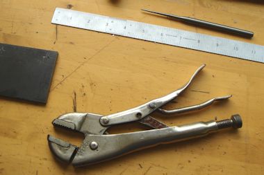
There are several different types of these quick release clamps around so first of check which you have as it makes a difference to the manufacturing process. The pair I had was actually an original Mole wrench which had been altered, bent and generally abused in a previous life (3). These and some copies use a bent sheet steel construction whilst others use a solid jaw riveted to the plate (4). Regardless of type the first job is to remove the lower jaw. If a sheet steel type this will require a hacksaw, I have already done this in (3) above. The other type requires drilling out the rivets to remove the jaw. Both types need the two upper jaw pivots drilling out. On mine I removed all the pivots so that I could straighten the bent parts out!
")
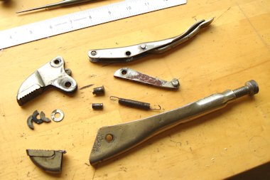
Once all is disassembled we can get down to making the new parts. All the bits of washers in photo (5) were inside the jaw where it had been cut out and welded up to increase capacity. I can′t imagine they added to the strength but the weld made it really difficult to file. I made a drawing of the various bits with some measurements but just use what you have and check the measurements of your drill table. Click on image (6) above for the full size drawing.
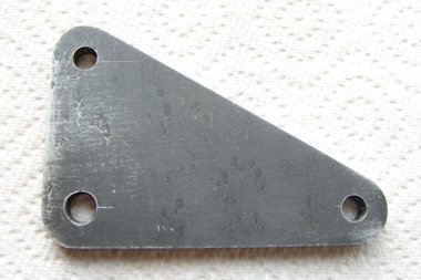
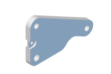
The first part to make is the replacement jaw, this is from a scrap bit of 6mm plate (the bit I had was probably ¼"), starting size needs to be about 110mm x 60mm. Mark out and drill the holes whilst still a rectangle, don′t forget to clamp it to the drill table! I started by making a triangle (7) using saw and file. To get the corners somewhere near circular use a couple of washers and a bolt as a guide (8). To make the relief for the moving jaw either saw and file or use the milling machine to achieve the shape shown in image (9), the relief increases the clamp capacity to about 40mm as seen in photo (10). The final job on this part is to cut the two pockets where the tension spring fits using an 8mm end mill.
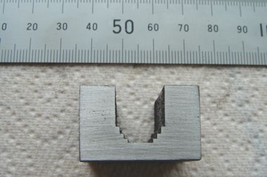
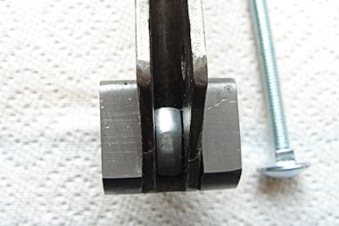
The baseplate or table hold down is the part that makes the whole thing work. This is from a block of mild steel 30mm x 25mm x 22mm with a U-shaped slot to fit the handle of the wrench. I cut this on the mill, as I don′t have a ball nose cutter I had to step mill (11) and finish with a round file. The file would have been necessary anyway as the handle was tapered so the slot needed to be 13mm at the front and 12mm at the back. The fit isn′t too critical though.
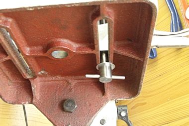
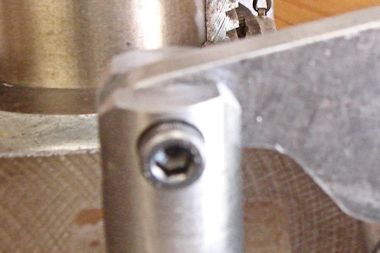
To hold the block to the wrench handle and ultimately to the drill table I made use of a 6mm coach bolt I had, this needs the head and square shank filing to fit the wrench handle (12). A round nut come spacer clamps the block to the handle and fits into the slot of the drill table, this part needs to fit the slots in your table in both width and length.
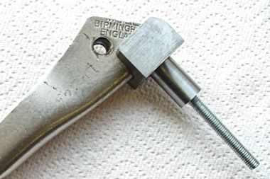
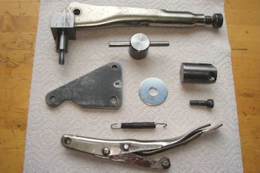
Photo (13) shows the lower handle assembly with the round nut in place, I added some Loctite when tightening up but this isn′t really necessary. The clamping nut that goes on the other end of the coach bolt to lock the lower jaw to the table is a simple turning job. Made from a 25mm length of 22mm diameter mild steel bar. Face both ends and drill and tap from one end 6mm about 20mm deep. Put a chamfer on both ends. Cross drill 6mm to take the tommy bar, a 65mm length of 6mm mild steel bar. This can be seen second item down in photo (14) and also on the right in graphic (15) below.
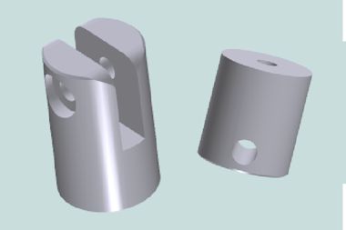
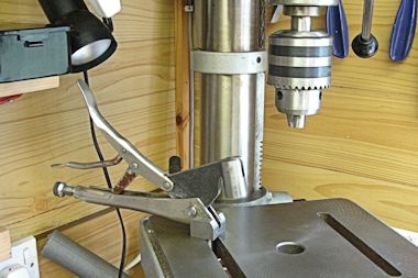
From the same 22mm bar cut a length of 35mm to make the clamp foot (15). Face both ends and chamfer. Mill out the slot using a 6mm end mill or slot drill. Cross drill 5mm (that is the 6mm tapping drill), open out one leg with a 6mm drill and counterbore 10mm 3mm deep to take the head of an allen headed bolt. Tap the other leg 6mm using the 6mm hole as a guide for the tap. The allen headed bolt is the pivot and the trick is to get the threaded section to bottom out at the same time as the head firms down into it′s counterbore, this stops the slot closing up as the bolt is tightened. Photo (16) shows the final assembly. There are just a couple of parts needed to fix everything together. A small pin and washer, fixed with a 4mm cap screw, to act as the pivot are simple turning jobs or you could just use a short length of rod and peen the ends over to form a rivet. Which is what I did for the smaller pins on the top moving handle. Photos (17) and (18) show the finished item on the drill table.