Stirling Engine
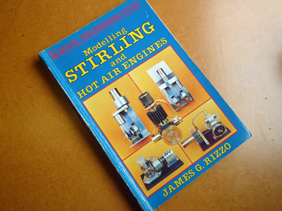
This is a small hot-air engine that can be made from what is available in the workshop. There is no complicated machining and it can be made easily just using a small lathe and hand tools. I made the original many years ago, it works well and has always been an easy starter. The engine is based on "Dolly" from James Rizzo′s Modelling Stirling and Hot Air Engines.
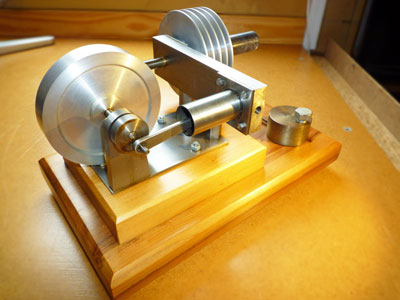
This is a true Stirling engine with a gamma configuration and is a simple introduction to this type of machine. As with most small hot-air engines the critical things are: to reduce friction, to have a very well fitting piston and to reduce dead air space where possible. This engine fails miserably on the last count! None of the dimensions are critical and really are made to fit the available tube size. I reverse engineered a drawing (3), if that is the right term, for anyone who fancies making their own version.

There are no pictures of machining operations as I made this engine way before the dawn of digital cameras. The first job is to have a good rummage about in the scrap box and select a suitable bit of thin wall seamless steel tube for the cylinders. The dimensions of the rest of the engine can be altered to fit. The drawing is in metric but the original engine was from imperial times. There were some really peculiar sizes when I measured up, probably as a result of most of the materials being derived from a skip (dumpster)!
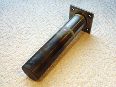
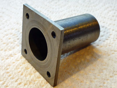
The displacer and power cylinders are made from the same size tube, the original is about ¾" OD. The method of construction is similar for both. The square mounting flanges are cut from stock and filed or machined to size, it will help to drill the four mounting holes whilst the stock is oversized as there is more to clamp up. Clamp the two blanks together using the mounting holes and file or machine to size. The centre hole can be drilled or milled to size but I mounted the originals in the four jaw chuck on the lathe and bored both to size at the same time. The hole needs to be a good but not tight fit on the tube to allow for solder penetration. The tubes need to be mounted in the lathe and the ends skimmed to make sure they are square.
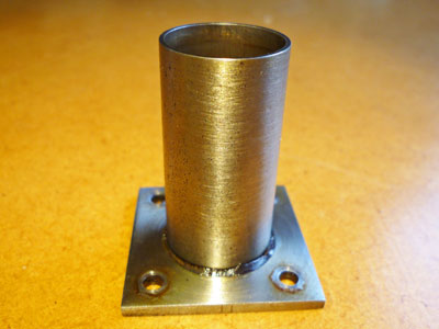
The mounting flanges and tubes will need to silver soldered (hard soldered) or brazed together. You might be able to weld with a MIG welder. Make sure when soldering that the flanges are square to the tube. Start with the power cylinder (5) as it is easier to hold vertical. I placed the flange on a flat fire brick with the tube supported vertically. Clean the join area, flux well and add small bits of solder (pallions) into the join area. Heat quickly using a good propane or mapp gas torch until the solder flows. Once cooled clean up and then mount the tube in the lathe and skim the flange to ensure it is square to the tube. Close the end of the displacer tube (6) by silver soldering a flat plate over the open end, it is easier to do this before fitting the flange, trim to match the tube diameter in the lathe.
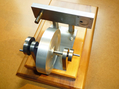
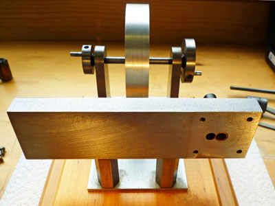
The base is just a rectangle of what is to hand, I think the original was from the end of a mild steel plate but a section of aluminium plate would be just as good possibly better. Once filed or machined to size it is just a matter of drilling and countersinking all the holes. If I were to make another I would use a thicker plate and counterbore the fixing holes for cap screws. The assembly uses countersunk screws to hold everything together. Four to mount the crank pillars and two to fix the cylinder block. The two hexagonal spacers beneath the cylinder block can be seen at (7). These could just as easily be round, they just need turning to length and a clearance hole for the fixing bolt drilled through the centre.
The cylinder mounting block can be seen in both (7) and (8) above and in the original is a length of BMS bar cut to size and filed square. The most difficult operation on this is the transfer port that goes lengthwise through the centre, drill this from both ends to meet in the middle. The power cylinder end needs tapping for a blanking plug. I realised when doing the drawing that the other end could also be tapped for a screw to retain the displacer bush / gland in place. The two sets of holes to mount the cylinders are most easily placed by clamping the cylinder flange to the block and spotting through the holes. Two holes underneath the block need to be drilled and tapped for the mounting screws. Again this can be easily done by clamping the base in place and spotting through with the drill.
The crankshaft pillars on the original were filed to shape but a milling machine would be easier. To file the circular tops I used filing buttons but the tops could be left square. Two tapped holes on the underside of each pillar are needed to mount to the base. There is a small brass bush fitted to each pillar for the crankshaft bearing, these are just turned and pressed in or could be held in place with Loctite or similar.
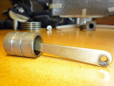
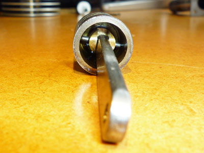
The power piston is a short length of cast iron or brass (9) turned to be a good fit in the cylinder tube. the inside of the tube will benefit from some lapping to get a good finish, this can be done in the lathe using a wooden dowel with some fine grinding paste. Once satisfied that the cylinder bore is suitably finished clean up well before trying the piston fit. Piston and cylinder can benefit from working together with a little metal polish. Test the fit by putting the piston, complete with yoke and conrod, in the bore and close one end of the cylinder with your thumb. When held vertically the piston should not move until the thumb seal is relaxed when the piston should descend slowly.
The piston has a separate yoke made from brass which serves to fit the conrod with a short length of rod acting as the wristpin (10). The brass yoke screws into the piston head and the wristpin cannot fall out as it is retained by the piston skirt. There are two small grooves in the piston which retain oil for lubrication, size and spacing is not critical.
The conrod is from a small section of BMS filed to shape after the two holes are driled for the wristpin and crankpin. There are no bearings as such although the bigend could be re-engineered to take a brass bush or small ballrace.
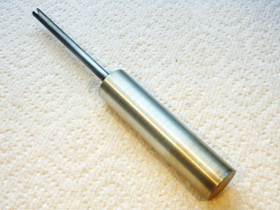
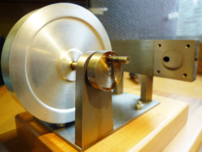
The displacer cylinder (hot cap) bolts onto the opposite side of the cylinder block to the power cylinder. The displacer rod is a good sliding fit in the brass bush / gland. This gland needs to be an interference fit and pressed into the cylinder block, adhesive will be no good here as it gets hot. The displacer gland is very close to the transfer port (11) and this hole might be easier to place after the bush is pressed in. The displacer gland bore should be reamed if possible and again this might be best carried out once pressed into place.
The displacer is made from aluminium tube with a plug pressed into either end (12) again no adhesive as it gets hot. Once the plugs are pressed into the tube, a long plug at the threaded end and a short one at the other, the displacer can be turned to length and the threaded hole for the displacer rod can be drilled and tapped in the lathe. The threaded end of the displacer rod should be screwed in tightly, hold the displacer in the 3-jaw and the rod in the tailstock chuck and turn by hand.
Hold the displacer assembly by the rod in the lathe and turn the outside of the displacer down to size, this will ensure that it is concentric to the rod. The small slot in the displacer rod end for the connecting link can be filed or milled and a small hole drilled for the pin. On mine the pin is just loose and hasn′t come out but a small spot of Loctite will secure it or a nut and bolt could be used. Don′t forget that the displacer isn′t a piston and has a clearance to allow the air to transfer from the hot end to the cold end of the displacer cylinder.
Most of the remaining parts are straightforward turning jobs. The two cranks are just discs with a crankpin pressed or Loctited into place. The cranks are secured with a grub screw to the crankshaft which is just a length of round BMS rod with the ends faced. When setting up the cranks are at 90° to each other, it doesn′t matter which way, the engine will just run in the opposite direction.
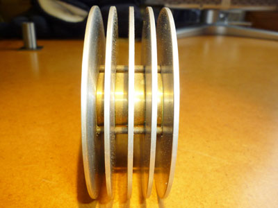
The cooler or radiator (13) is made from five circles of aluminium sheet (16SWG originally) and four brass spacers. The cooler assembly is held together by four long bolts and nuts and slides onto the displacer cylinder with a little heat conducting paste, the sort that is used for electronics heatsinks. The most difficult bit making the cooler is to keep the sheet flat, I cut the originals using a jigsaw. Mark out the hole positions, clamp all the plates together and drill the four clamping holes and a 10 or 12mm hole in the centre. Mount on a mandrel, a bit of threaded rod and a couple of nuts and washers works well, and gently turn the outside to diameter. Clamp the five plates together using the four mounting holes. The centre hole can then be bored on the lathe using the three jaw chuck with reversed jaws so that the plate stack can be pushed firmly against the jaw step to ensure it is vertical. Remove and deburr the plate edges.
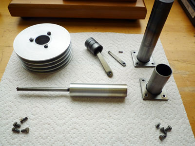
The spacers are from brass rod, turn to size, drill and bore the centre hole to fit the displacer cylinder tube and then part off four rings. Assemble the cooler with four bolts and nuts, I only used three bolts on the original but the heads interfere with the displacer cylinder mounting bolts. The last photo (14) shows the parts that I removed from the engine laid out ready to reassemble. I think the only part I have not mentioned so far is the displacer link which can be seen next to the piston, this is just from a small bit of BMS strip, filed to shape with two holes drilled.
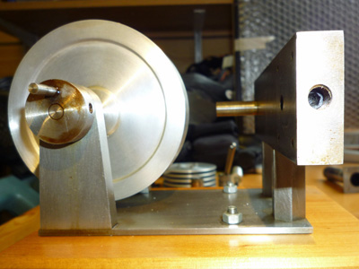
The flywheel can be made from whatever is to hand, the original was from aluminium and had the barest of recesses in the faces. It had no fixing screw and was just pressed onto the shaft but I have drawn the new one with deeper recesses and a means of fixing to the crankshaft. To make the deeper recesses mount in the lathe and use a tool similar in shape to a parting tool which is plunged into the flywheel face a process I believe is called trepanning, the front of the tool needs plenty of clearance to miss the side of the recess. Also in this photo (15) you can see the blanking screw at the power piston end of the transfer port.
Finally (16) a short video of the engine running. It is very quiet and the camera barely picks up the sound. The burner can be to any design that will fit under the hot cap, it may even run on a T-light although I have not tried it.
A fairly simple beginners project open to all sorts of embelishment and modification. I mentioned at the start that this engine had too much dead air space for efficiency, this could be improved by making the whole thing narrower thus reducing the transfer port length which is where most space is wasted. For those interested in wood, the base is from a very old plank of Parana Pine, I don′t think it is obtainable in the U.K. anymore.