Prusa i3 Style 3D Printer
I thought it was about time to become a "maker" and try 3D printing. There are many different types of 3D printer available and you can spend as little or as much as you want to get going. My interest was peaked by a few posts on the Model Engineer Forum and a review of a Dremel printer (expensive) in Model Engineers Workshop. I opted to go for a kit based on the open source Prusa i3 design. I chose a kit over ready to run partly because of the the cost but probably more for the challenge of building it and hopefully learning a bit more about 3D printers in the process.
This style of printer is often supplied as a kit but is also available ready to run. The original Prusa kit will set you back £629.00 and ready to run £899.00 (as at August 2017). The design is open source and there are many suppliers and numerous variations. You can get plenty of different kits from Amazon, most are of far east origin and you need to read the specifications carefully, some are plastic framed, some metal and even some wooden versions. Most use pretty standard electronics and again you can source most of the parts seperately through Amazon if you fancy starting from scratch. What you can′t get quite as easily are all the printed parts that hold everything together.


I bought my kit from Factory 3D, a small firm based in Newcastle-upon-Tyne in the UK. This particular kit is not the cheapest but is well priced and complete. Most important for me was that it used 6mm aluminium plate for the main frame and the build plate support. After sales support was reported as good and indeed, having hit a minor problem with the SD card reader, I can say that it is excellent. This is not a kit you can just clip together, you will need tools, at a minimum several spanners, screwdrivers and allen keys. You can opt for an extra package with the kit which includes some of the tools you will need. Sales are through Ebay and you may well find that the printer kit is not listed. Basically they are sold out as soon as a batch is made which must be a recommendation in it′s own right. Their website is fairly basic but if you contact them by e-mail the response is pretty quick.
Assembling The Kit
This isn′t intended to be a detailed piece by piece build but more of an overview. There is an 80 page manual with the kit, another reason to buy this particular version and there are numerous full builds of this style of printer on the interweb with plenty of U-tube videos. You can visit the Prusa website and they too have a full online build manual. I did though make a few changes as I went along and will describe these in a bit more detail.
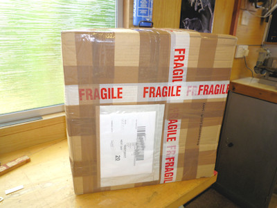

The kit comes well packed in a large box (3), all the parts are individually wrapped and labelled so you know what′s what. There are about 20 individual boxes and packets (4) each labelled and grouped into sensible lots so that you don′t need to open everything at once. For example all the rods are wrapped and inside a stout cardboard tube and all the bits you need to start on the Y-axis are in one bag. You don′t need to do anything to the parts, the rods are cut to length and I found that all the nuts went straight on. I did though spend a little time running my deburring tool over the main Z-axis frame and the build plate support which are supplied just as waterjet cut. I also found that the small holes in the aluminium plates still contained some abrasive powder from the waterjet. You may want to poke a bolt through each hole to clear it out, you don′t want the abrasive in your bearings!

Y-Axis
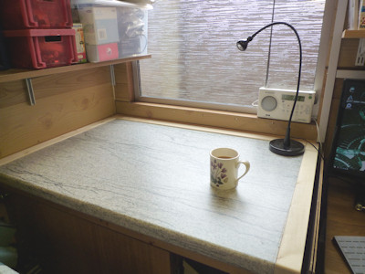
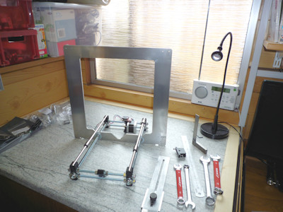
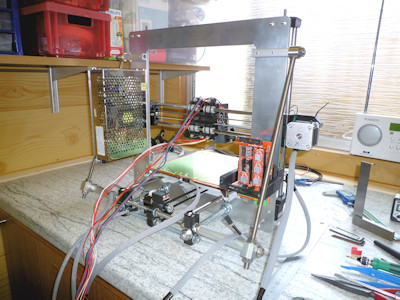
First thing you need is somewhere to work, you really need a nice flat surface so that the assembly is level. This design of frame using threaded rod isn′t particularly rigid so a good stout build surface is ideal. I cleared the top of my cupboard and laid a kitchen worktop offcut down (5) to supplement what was already a pretty solid top.
The place to start, so the manual says, is with the Y-axis. This is basically 6 threaded rods held together with plastic corners and lots of nuts and washers. Interestingly the corners and other plastic parts are 3D printed in PLA, using the same printer. The files to print all the plastic parts are included on the SD card that comes with the kit, so once you have your printer working you can print the parts to make another! The assembly was quite easy and went together in about 20 minutes, the longest job is probably running the nuts down the threaded rods, quite a few are near the centre of the rods.
You can see from the picture (6) (from the manual) how the Y-axis motor is fitted to it′s bracket on the frame. The Y-axis limit switch is also mounted on this bracket and there is just enough slack where the bracket fits to the rods to allow adjustment of the switch up and down to align with the build plate. The manual has a section explaining how to extend the motor leads where needed but I found this had already been done for all the motors. Each motor is in fact marked so that you know where to fit it as all the cable lengths are different.
Mod 1 - Bearing Change
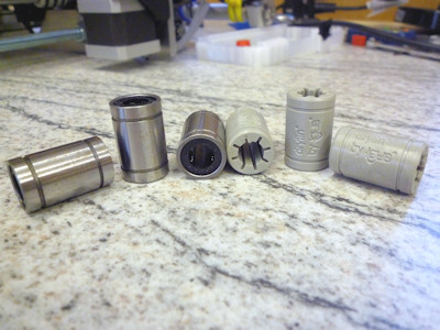
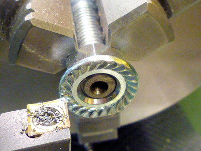
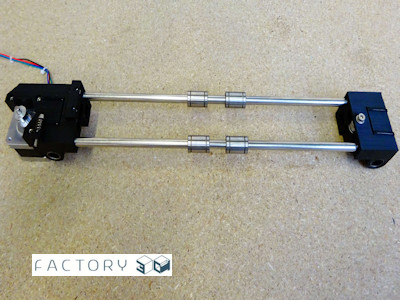
It didn′t take me long to deviate from the master plan. Having got the Y-axis together I couldn′t resist placing the build plate support on the three linear bearings and running it up and down. I thought that the bearings felt a bit gritty, I tried different bearings from the kit but they were all the same and individually felt loose on the rails. The LM8UU linear bearings supplied with the kit are pretty standard and basically very cheap, all these printers including Prusa use the same type. There are only 4 rows of very small ball bearings in each shell. I tried one or two on the other 8mm rods but no improvement. I decided to swap them out for Igus DryLin RJ4JP-01-08 plastic bearings (7). These seem to be a tighter fit and are definitely much smoother. These Drylin bearings are a direct replacement, exactly the same size, but really benefit from being a tightish push fit in their housing. I think the bearings in the X and Z seem a better fit on the rods (might be my imagination). I have noticed that some versions of the printer have the Y-axis bearings in a proper housing rather than just cable (zip) tied to the plate, a future upgrade possibly. In the interim I drilled extra holes in the build plate support and added extra zip-ties (8), it does seem to make the build plate less prone to sideways wobbble.
Z-axis & Build Plate
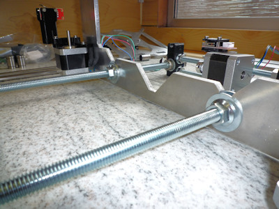
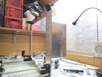
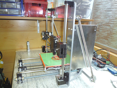
This axis consists of a large 6mm pre-cut metal plate which carries the Z motors and the vertical 8mm rails. The motors are fixed to brackets at the lower corners of the plate (9) the brackets are also the fixing point for the vertical rails. First job is to fix the plate to the Y-axis frame simply by slotting the plate onto the 10mm threaded rods and tightening the nuts either side. Quite straightforward and well explained in the manual. You end up with something like the assembly in picture (10).
The Z-axis setup continues with adding the motor brackets including the Z-axis limit switch and the top rail support brackets. The brackets are bolted on with M3 nuts bolts and washers which come in the bag. The rails are added later when assembling the X-axis.
The build continues by adding the build plate, the heated bed and the belt drive. The belt fixing is bolted to the underside of the build plate and then the plate can be zip-tied to the bearings (see mod 1). It is at this point that the Y-axis frame can be adjusted to ensure that the build plate glides smoothly through its full travel. This needs to be done before fixing the belt. However, I found that simply releasing the grub screws on the motor pulley allows the build plate to be pushed up and down easily which is also useful for checking the belt alignment. Now is the time to check that all is square in both horizontal and vertical planes. It is worth spending some time at this stage to ensure future accuracy, the manual says as much and I would suggest reading the manual through a couple of times before starting the build.
The manual recommends starting some of the wiring at this stage but it depends to a certain degree how you are going to finalize the cable runs as to how far you can get. I wanted to put the cables in braided sheath so that really needs to be done a bit nearer the end. To keep cables out of the way I temporarily taped them to the frame where they wouldn′t get damaged or pulled.
Mod 2 - Z-Axis Plate Fixings
Trying to get the z-axis plate vertical I found very difficult, it seemed OK until I tightened up the nuts when it would lean one way or the other. As far as I can tell this is mainly caused by the thread in the nut not being at 90° to the face of the nut. I also noticed that there were some hefty burrs on the washers which probably didn′t help. Not really surprising as nuts, washers and threaded rod are not really precision items. It wasn′t far out but enough to annoy me!
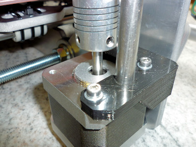
I altered the fixing slightly. First I removed the burrs on the washers by rubbing on a sheet of abrasive paper on a flat surface. I then found 4 M10 flange nuts and turned the face of the nut on the lathe (11) to make it as near as possible perpendicular to the nut thread. I did this by holding a length of studding in the chuck and screwing on the nut, flange outwards and facing off the serrations to make the flange smooth. With these two slight modifications I found the Z-axis plate was much nearer to vertical. It looks much the same as the original but (12) is a picture of the mod in place.
Mod 3 - Z-Axis Frame Brace
At this point I got slightly carried away with re-engineering things! I noticed that the top of the Z-axis support plate could easily be moved to and fro and decided that some form of bracing was in order. The plate is pretty substantial at 6mm so is not going to bend a great deal but the rods that support it can easily flex slightly. Pictures of early Rep-Rap printers show a mass of diagonal bracing and some of the Prusa builds include printed bracing brackets under the plate and some, usually the plastic versions, have a gusset plate of some descripion. I decided to add a rear support brace made from 8mm studding that I had to hand.
To add the frame braces I needed to make some anchor points, two at the top of the Z-axis frame and two somewhere at the lower rear. The top fixing was fairly easy, I found a bit of square thick wall aluminium tube (I don′t know what it was in a previous life). I turned a couple of M8 threaded studs to fit inside the tube and glued them in. Added two M3 tapped holes and screwed them to the top of the plate (13).
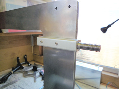
To fix the brace at the rear I replaced the top M8 threaded rod in the Y-axis frame with a much longer one. This extended the fixing point out to the same distance as the top anchor points but M8 studding is fairly bendy. To brace the extended studding I made up a tube with a couple of top-hat washers (14). This assembly fits over the studding and once the nuts are tightened the studding is in tension and much stiffer.
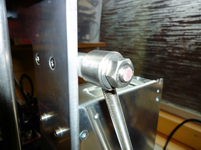
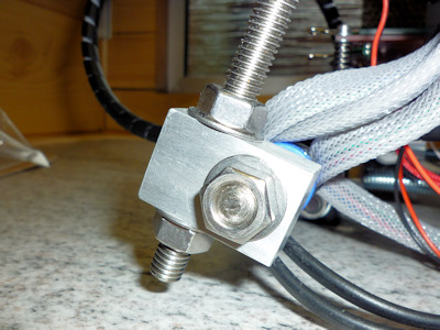
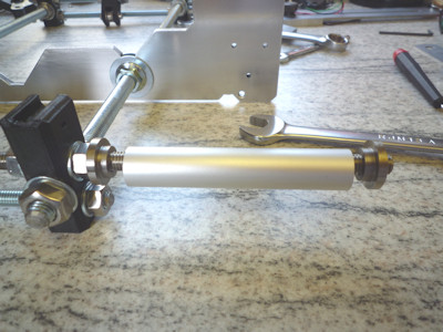
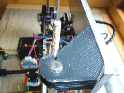
The diagonal brace is just a length of 8mm studding. The top is screwed and glued into a 15mm length of 19mm diameter stainless steel with an 8mm hole along it′s axis (15). The bottom of the brace is just plain and takes two nuts and washers which fit either side of the lower anchor point. The anchor is a 30mm x 20mm x 15mm aluminium block with two 8mm holes (16). The two nuts allow the brace length to be adjusted to ensure the Z-axis plate is vertical.
While I was fitting the Z-axis plate I added three holes to let me screw the power supply to the frame (17). There are 3 conveniently placed pre-threaded holes in the side of the power supply case, so just a matter of some careful marking out. I made good use of the drill press and de-burred all the holes in the plate at the same time by adding small countersinks. Photo (18) shows how the finished brace fits and clears the power supply.
X-axis
Having gone off at a bit of a tangent with the angle brace and power supply it is time to get back to the build. Really it is just a matter of following the manual it pretty well covers everything step by step. Before you can fit the Z-axis rods into their brackets you need to assemble the X-axis. Nothing too complicated and it is well explained. The X-axis rods are a push fit into the left and right bearing housings (19). The fit is quite tight, I had to exert quite a lot of pressure to get the top left rod home. Don′t forget to put the bearings on the rods before assembly.
Now that the X-axis is assembled it can be mounted onto the Z-axis rails by sliding the rods down through the top mount (20) , through the bearings and down into the bottom bracket (9 above). One thing I did find was that the 8mm Z-axis rods are a really tight fit in these brackets particularly at the bottom which is also the motor mount. The holes have slots to allow the bracket to open slightly as the rod is pushed in but they are still very tight. I was loathe to push down really hard on the bottom bracket and motor and ended up removing the motor and brackets and trying the rod on the bench. I think possibly a slight burr on the plastic bracket but once I had got the rod in it was much easier second time around. I would suggest trying the fit of these parts before assembly, it is also a good idea to leave the front motor screw slightly loose so that the slot in the bracket can open up as you push the rod in.
I attached the X-axis carriage, it is a nice positive click fit on the bearings. Sliding left and right it was noticeable stiff on the left side. A quick measurement revealed that the rods were slightly further apart on the left hand side something in the order of 0.02mm to 0.05mm, difficult to measure but easy to feel. Reasoning that the very stiff fit of the top rod might be the cause I removed the x-axis and took it apart, needless to say the top rod did not want to come out and I had to hold one end in the bench vice (carefully protected with a paper wrap) and twisted and pulled the left bearing housing off. I resorted to some fairly crude engineering to make the adjustment. A suitable riffler file applied to the lower face of the hole just a couple of strokes and then ran an 8mm reamer down the hole. The end of a hand reamer is slightly tapered so the hole was still going to be tight but hopefully a fraction lower. Reassembly of the X-axis and carriage confirmed that I had got it right I am pleased to say and the movement is smooth and even for it′s full travel.

Having now got X, Y and Z movement all nice and smooth it was time to fit the important bit. The hot-end and extruder assembly (21). This is largely ready to go but needs it's support framework adding and the build plate fans bolting on, all well explained in the manual, there are actually 6 pages covering the extruder assembly and if you click on the photo you can see a typical manual page. The only thing to be aware of with this assembly is that it is "handed" starting with the X-axis carriage check carefully before you zip-tie the bearings in place you don′t want it upside down or back to front!
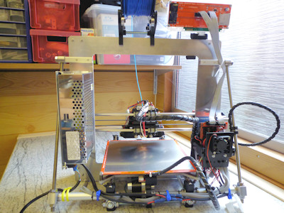
Once the extruder is on board that is pretty well the end of the mechanical build and it remains to wire everything together. A rear view shows most of the wiring (22) hanging out ready to go.
Wiring Up
All the cables from motors switches, heated bed and extruder go back to one place the RAMPS board (RepRap Arduino Mega Pololu Shield) some 64 wires by my reckoning. The manual refers in the main to the RAMPS board as one entity but in reality this is several different bits of electronics.


There is the brains of the outfit an Arduino Mega (23) powered by an ATmega2560 microcontroller chip. The RAMPS board (24) which provides all the connections to the outside world which plugs on top of the Arduino Mega. Then there are 4 Pololu A4988 stepper motor drivers which plug into the RAMPS board. Lastly a small header board which connects to the LCD and SD card reader via two 10 way ribbon cables. This all comes pre-assembled in the kit and has been adjusted and tuned so that it is ready to go, even the LCD board is plugged in though you may want to remove the ribbon cables whilst building.
You don′t need anything extra to complete the wiring, there are a stack of cable (zip) ties in the kit in various sizes to secure all the wires into sensible looms and to secure to the frame where needed. Being me I decided to make a few changes on the way!
Mod 4 - Wiring
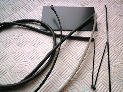
The main change I made was to enclose all the wiring in braided nylon sheath, mainly to keep all the cables together but it also provides somewhere to tidy away any spare cable length. As well as the nylon sheath I also used spiral wrap (25) to stiffen and shape the wiring looms that needed to move. As I said earlier most of the wiring is already the right length but it depends how you run the cables. I lengthened the X-axis motor cable a bit and the sheathing hides the join. All the bits to do this are in the kit, spare connectors, heat shrink tube and wire. I tried not to alter the cables too much - did I mention that I now have a great dislike for Dupont connectors, the plugs on the ends of the motor leads. Despite having a crimping tool that is supposed to do everything it wouldn′t work with these tiny connectors, apart from having great difficulty seeing the damn things in the first place!
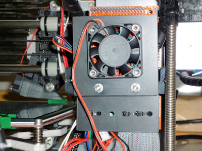
The braided sheath expands quite a bit so it is easy to work the plugs through. The only drawback is that the ends of the sheath fray very easily. Once past the plugs I wrapped a bit of insulation tape around the sheath and cut of the hairy end! The ends of the cable looms need to be fixed to something so that the wires can be spread out to reach their respective pins on the RAMPS board. Some of the cable looms can be zip-tied to the frame but there are no easy fixings below the RAMPS board so I added a small panel (26) made from styrene sheet with holes for the zip-ties. I also made a plate to mount the RAMPS fan from the same styrene sheet, if you just mount it to the supplied bracket part of the flow is blocked, it also makes it easier to remove the fan if you need to tweak the motor drivers.

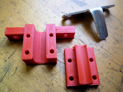
Another wiring change was to add some anchor points for X-axis wiring loom. This runs from the extruder to the RAMPS board and has to move both up and down and side to side. There is nothing really suitable on the extruder assembly to secure all the 12 wires to, so I made a small aluminium bracket and zip-tied the wiring loom to this. I drilled a couple of holes in the RAMPS mount for zip-ties to secure the other end of the loom. Photo (27) shows the cable clamp bracket on the X-axis carriage and the zip-ties on the RAMPS bracket (click the image for a larger version). I subsequently replaced the aluminium bracket with a two part printed clamp (28), it took me a couple of goes to get it right, but hey, it′s only plastic, the picture is one that was almost right! A useful change to the hot end wiring is suggested in the manual, which is to split the wires from the heater and thermistor with a couple of connectors. The parts are included if you want to do this, I found it makes removing the hot end much easier.
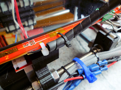
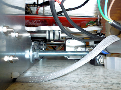
Minor mod on the Y-axis connection, it needs to be fixed to the hot bed and there are no obvious clamping points. The best I could come up with was to add an extra zip-tie using one of the holes in the pcb, not sure if this was a good move or not but it does clamp the spiral wrap to the table, the other end is simply zip-tied to the frame. Photo (30) shows a view from the rear and you can see that the spiral wrap over the braided sleeve holds itself in place without using any extra support.
Final Connections & Switch On
The most important thing with the final wiring is to check and double check where you are plugging the cables into the RAMPS board. It is very crowded and remarkably small and there are quite a few spare pins about. Take particular care with the end-stop cables as they plug into every other set of pins on the board with an unused set of pins in between.

Most of the wiring to my RAMPS board is coming up from below (31)and I tried to space it out so that the air from the fan would be able to pass through the wiring and get to the heatsinks on the motor drivers, not easy as there isn′t much space. The headers at the top and right of the image are where the LCD and SD card reader cables attach.
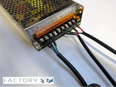
The last thing to wire up is the power supply (32), the connectors come ready made so it is just a matter of attaching at either end. Conveniently the connection between the RAMPS board and the power supply is in two parts. This makes life easy as you can connect the power supply wires when flat on the bench and then, in my case, bolt the supply to the frame. There are a set of spade (Lucar) connecters to join everything up.
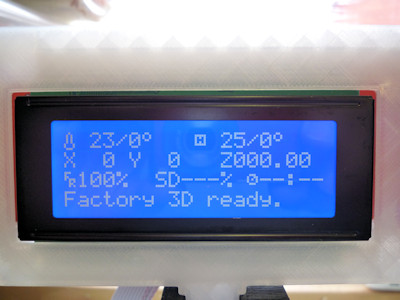

The manual has very clear instructions for powering up for the first time, I followed these and everything worked. All being well you should see the startup message on the LCD screen (33) and nothing should move until you tell it to. Once everything appears to work the printer needs to be set up, homeing checked and the bed levelled. Again this is all cleary documented in the manual.
Software
Before you can print your own files you need to install some software on your PC. The printer reads g-code (RS-274 a numerical control programming language), to get this you need first to draw your part (I use Alibre). Export your drawing as an STL file. Use a slicing program to convert the STL file into layers. Output the result of slicing as g-code onto an SD card. Put the SD card in the printer and print it.
There are some ready to go g-code files on the SD card that comes with the printer. These are in fact the files to make the parts of the printer, the simplest is for the dust trap which was my first print. The software you need to prepare your own files is also on the SD card. The printer comes with Cura 14.12.1 that has already been setup to work with the printer. Once installed Cura will slice your STL files into g-code ready to print. Other software on the card is Marlin, this is basically the firmware to drive the printer. If you want to get into altering this you will need the Arduino IDE installed on your PC
The recommendation is to print from an SD card and not directly from your PC. One of my early test pieces was Benchy (34), file available from Thingiverse, which is apparently quite a tough test for the printer, with plenty of overhangs and bridges. I now have quite a fleet, some more seaworthy than others!
Conclusion
The kit as supplied is very good, it is complete and has everything you need to get a working 3D printer. I had a problem with the SD card reader and the response from 3D Factory was very quick, helpful and the part was replaced without any problem or delay. They also respond to e-mail very quickly and were quite happy to answer my "nooby" questions. My thanks to Factory 3D for allowing me to use some of their photos above.
The Kit Pros
- Delivered on time
- Well packed with sub assemblies in individual packs
- All necessary hardware included (no machining required)
- Spare pack of nuts, bolts etc. Spare electrical parts
- Optional tool and consumables pack
- Plenty of zip-ties
- Comes with all necessary software on SD card
- Excellent 80 page manual
- Good after sales service
- Well thought out implementation of a design classic
The Kit Cons
- Requires a level of mechanical and electrical experience
- Needs some measuring equipment to set up accurately
- Hot-end mounting system makes maintenance access difficult
- Power supply terminals could do with safer enclosure (can be retro printed)
- Build plate fan fitting very awkward when you need to remove them
- No easy cable fixing points for the flexible wiring
Overall a very good introduction to 3D printing especially if you have the Meccano gene! Nicely put together selection of parts to complete a pretty good working printer. The bits I have made so far have been very good but there is definitely a bit of a learning curve to get the best results from the software. I have a lot of learning yet to do...
Info, Links & Glossary
Factory 3D - Supplied the kit I built, very helpful. If the kit isn′t listed on E-bay it is worth sending an e-mail.
Prusa 3D Printers - The Prusa design has been evolving for a good number of years and there are probably tens of thousands out in the wild. The design is simple, easy to put together and easily adaptable. All the parts used are available individually and are remarkably cheap to buy. You will need things like spare extruder nozzles apparently they wear out quite quickly but they are only a few pence each. It is worth having a look at the web site, plenty of useful information.
Arduino - get the IDE from here if you need to play with the printer firmware.
Marlin - software that runs the printer (for the advanced user / programmer)!
CURA - the slicing software, this is from Ultimaker and the software is free to download. Be aware that you will probably only find the latest version (2.6) from here and it wont work with this printer without a good deal of tweaking.
FDM - fused deposition modelling, thats 3d printing
STL - STereo Lithography (sometimes Standard Triangle Language) file format used to store 3D shape
PLA - Polylactic Acid, common plastic used for 3D printing
ABS - Acrylonitrile Butadiene Styrene, another commonly used plastic for 3D printing
RAMPS - RepRap Arduino Mega Pololu Shield, this is the circuit board that all the printer components connect to
Arduino Mega 2560 - The micro controller board that controls the printer
Dupont Connector - the small multi-pin plugs on the wires from switches and motors that fit the pins on the RAMPS.
g-code - RS-274 a numerical control programming language, tells the printer what to do
SD card - Secure Digital, a non-volatile memory card format for use in portable devices.
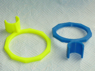
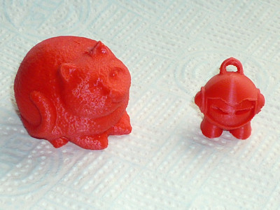
Of course once you get into 3D printing you will quickly discover that you can make anything from the moderately useful (35) clip on cup holders for a wheelchair. To the completely useless (36) a fat cat and Marvin - who is Marvin anyway?