Fitting A Quick Change Toolpost To The WM250
Now at first glance this would seem to be a pretty straightforward job; viz. buy toolpost, put on lathe, tighten nut. Not so. This is one of those chicken and egg jobs; to fit the toolpost the top-slide needs machining on the lathe, without the top-slide I can′t fit a toolpost...
This "simple" job grew somewhat and one thing led to another so there are two pages. The first page covers my choice of toolpost and details the making of a completely new toolpost assembly to fit directly to the cross-slide. The second page deals with making a new clamp plate for the top-slide and modifying the top-slide to take the QCTP together with the necessary T-nuts and other parts to fit everything together.
The QCTP
First a quick digression into my choice of toolpost. There are several different styles of QCTP but broadly speaking there are those based around the Dickson style often referred to as Myford-Dickson, those based on the Aloris style and variations on the Multifix theme. All the originals are very expensive so the Chinese copies come into their own for home workshop use. I have always thought that the Dickson style tool holders look very complicated and it would be impossible to machine spares easily. The Aloris style holders are more straightforward and could at a pinch be machined in the home workshop (the holders are also much cheaper to buy ready-made). The Multifix types always seem to be very expensive in comparison to the others.
The Aloris style toolpost comes in two variants, piston and wedge. The piston type forces the holder out from the post and locks in place using the tapered sides of the dovetail. The wedge type pulls the holder back against the post and locks in place using both the dovetails and the flat face of the holder. Manufacturers claim that the repeatability and accuracy of the wedge type is slightly better than the piston type. The piston type is widely available in the UK but I was unable to find a stockist for the wedge type. In the end I brought a wedge type from Tools-4-Cheap in the US and a toolpost set (including shipping) was cheaper than buying a piston style set in the UK Fortunately the holders for both types are interchangeable and Arc Eurotrade sell them quite reasonably. There are several different sizes but the one to suit this lathe is usually designated as AXA or series 100.
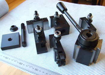
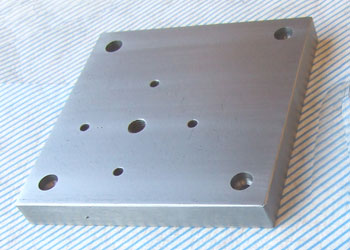
The toolpost set includes the toolpost, five holders, a mounting stud, clamping nut and a plate to be machined to fit a t-slot on the lathe (1). The holders are: standard to take a 12mm tool, heavy duty boring tool, parting blade, standard / small boring bar and a knurling tool which doubles as a tool holder. The mounting stud is 14.3mm diameter and threaded 9/16" UNC which is much larger than the stud fitted to the top-slide (10mm with an 8mm threaded section).
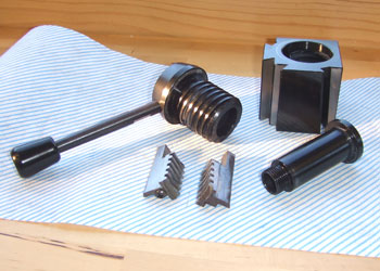
I took the toolpost apart to clean and to see how it worked (2). The centre tube on the right of the photo holds everything together, the bottom section is a left hand thread which screws into the base of the block. The larger threaded tube that does the work is a three start left hand acme thread for those that might like to make their own! The three start thread gives relatively large vertical movement to the wedges for just a part turn and can be used to change the handle locking position.
With hindsight and a few years use I wouldn't recommend buying a set. Some of the holders I have not used and am unlikely to do so. Better to buy just the toolpost and as many plain holders as you need.
Cross-slide Tool Post
The top-slide has a cast in spigot which helps support the original toolpost clamping stud. This will need turning down to fit the new QC toolpost as the toolpost central bore cannot be altered. This meant making a new toolpost that could be fitted directly to the cross-slide. The cross-slide toolpost is in three main sections, the base or mounting plate, the plinth and the clamping stud. I made the mounting plate (base) of this toolpost at the same time as the 4 Bolt Clamp. There are also a couple of small extras that are needed to complete the job, namely a thick clamping washer, four t-nuts and M6 cap screws, four M5 cap screws for fixing and a small countersunk washer and screw to replace the cross-slide nut fixing screw.
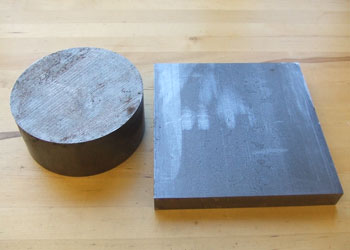

The base for the toolpost is simply a 125mm (5") square of 15mm (5/8") BMS. My cross-slide measured 126mm so not 5" or the nearest metric bar size 125mm, it is not critical. Even though the U.K. is supposed to be metric I couldn′t source 125mm x 15mm flat (unless I wanted rather a lot). I ordered two 5" lengths cut from a 5" x 5/8" BMS flat supplied by M-Machine in Darlington. I also ordered a short length of 3½" bar for the plinth (3). I had a suitable stock bar to manufacture the stud from. The drawing (click on photo (4) for a larger readable version) gives approximate sizes but if you are tempted to make your own please double check the dimensions applicable to your lathe.
The Mounting Plate
The two bits of bar I had were reasonably clean and square and could have been brought to size by filing but this would definitely be hard work. I used the milling machine with a 16mm endmill to do the work.
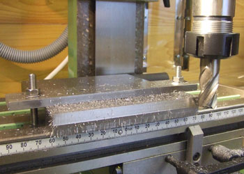
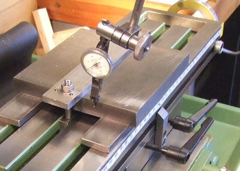
The first operation I carried out was to machine the edges of the two 125mm (5") squares. I used my mini mill to do this and it coped quite well (5). I wasn′t too concerned about size but did my best to get them square, I only machined the band sawn edges as the other two were reasonably clean. Once both plates were complete I deburred the edges and corners and marked out the drilling positions. Back to the milling machine and set the plate square for drilling and counterboring (6).
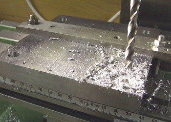
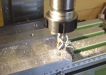
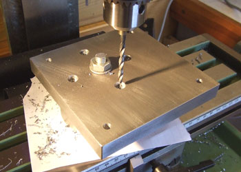
I used the mill to drill and counterbore the mounting holes to try and maintain accuracy using the X and Y slides to position the drill. I used a centre (slocombe) drill first and then straight through with the 6mm drill (7). Technically the proper clearance drill for an M6 bolt is 6.2mm but I didn′t have one of those and 6mm is quite a free fit. I didn′t have a 10mm counterbore either so I used a 10mm end mill (8). This meant a change of chuck but the mill has a dovetail Z axis so no problems raising and lowering the mill head.
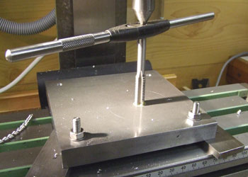
I prepared both 5" squares at the same time to the stage of drilling and counterboring the 4 mounting holes. I then set one aside for the 4-bolt clamp and continued with the cross-slide toolpost. At this stage the plate needs turning over to mark out and drill the hole for the stud and the four fixing bolts. Once marked out I used the corner mounting holes to clamp the plate to the mill table. The first job was to drill and tap M10 for the clamping stud (9). I was going to put the stud dead centre but thought it might be useful to offset it so that I can now position the toolpost at any one of four positions. These operations were carried out at the same setting to ensure that everything was aligned. I used a centre in the mill taper to keep the tap vertical and applied light pressure on the quill whilst tapping. You can just make out the centre pops for the fixing bolts and these were drilled to clear M5 and counterbored for cap head allen screws. After a bit of cleaning up and deburring the finished base can be seen in photo (10).
The Plinth
The plinth supports the toolpost at the correct height. I thought it was a good idea to set the top of the new plinth at the same height as the top of the top-slide. Thus once the tool height was set on the new QCTP holders they could be used with the toolpost on either mounting. The height of the top of the top-slide from the cross-slide on my lathe was 50.5mm yours may be different!
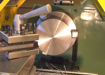
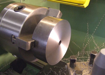
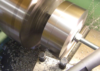
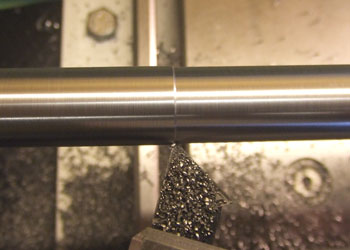
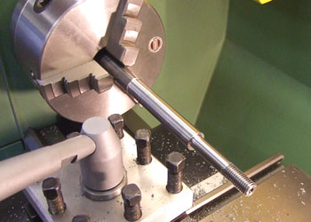
This is a straight forward turning job. The bar stock is mounted in the 3-jaw chuck fitted with reverse jaws and faced (11). Turn over and making sure that the bar is firmly against the step in the chuck jaws face to thickness. This is the critical measurement for the height of the plinth plus the thickness of the plate should equal the height of the top-slide from the cross-slide. On my lathe with the materials I was using this was 34.75mm. Once to the right size drill through 10mm for the clamping stud (12).
To turn the outside diameter of the plinth I used a mandrel made from a short length of 10mm studding. I put a centre in one end and locked a couple of nuts onto the opposite end (13). I held the mandrel in the 3-jaw chuck with the nuts up against the rear of the jaws and then tightened up the outside nut, clamping the plinth in place with a washer and a piece of paper to protect the finish. M10 studding is readily available in many large DIY stores and is a good fit in a drilled 10mm hole, I found that one wrap of paper around the studding ensured that the plinth was a good tight and centred fit. With the tailstock centre engaged I turned the plinth down to 82mm diameter, not a critical size but it looks about right with the QCTP mounted. I also put a chamfer on the top corner about 2mm wide (14).
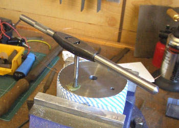
I suppose you could argue that one M10 bolt at the centre of the plinth would adequately hold it in place on the base but I added four M5 cap screws "just to make sure". I used a piece of M10 studding to hold the base and plinth to the milling table, the piece of paper is to protect the finish on the top of the plinth (15). I spotted through each fixing hole with a 5mm drill about 2mm into the plinth and then drilled the tapping size to depth. I tapped the fixing holes on the bench as the small taps don′t have centres and in the chuck I couldn′t feel what was going on (16). I started the tap square by using a small V-block, the yellow gunge around the tap is Trefolex tapping compound, smells foul but works well.
The Clamping Stud
The next part to make is the stud that holds everything together and mounts the toolpost. This was turned from a length of 18mm free-cutting BMS.
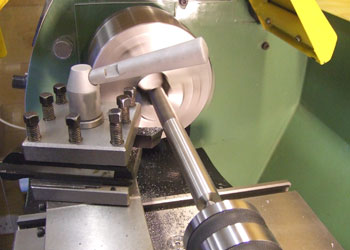
I put a small centre in one end and then held the stock bar in the three jaw (17). This worked well and I was pleased with the finish I obtained using a carbide tipped tool (18). I reduced the whole length to 14.3mm diameter to fit the toolpost and then further reduced the tailstock end to 10mm diameter for a length of 50mm.
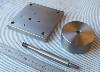
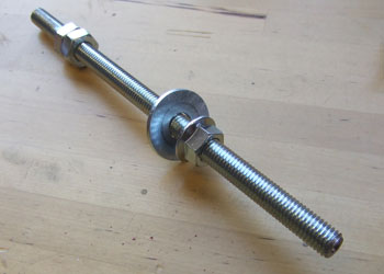
Once the diameter was at 10mm I cut the M10 thread 20mm long using a tailstock die holder. I did think about screw cutting in the lathe but decided against it due to lack of experience, although I'll never get the experience if I don′t do it! With the bottom end complete (19) I removed the stock bar from the lathe and cut off the stud to length. Reverse the stud in the 3-jaw to reduce the top 22mm to 8mm diameter and cut an M8 thread to suit the existing toolpost clamp lever. Photo (20) shows the three main parts of the cross-slide Tool Post ready for assembly.
The second part of this project deals with some of the parts that are common to both the cross-slide toolpost and for the 4 bolt clamp. All the finished parts and the final assemblies are shown and the QCTP is finally mounted on the top-slide.