New Lathes For Old
For many years I had an old Myford ML7 lathe which I purchased second (or possibly fifth) hand rather a long time ago. The Myford had seen plenty of use when I bought it, had quite a few hacksaw marks on the bed and the chuck had definitely hit the saddle more than once. I was going to get it refurbished but the cost of a bed regrind, new motor, new leadscrew and new bearings far outweighed the cost of a brand new Chinese model. I decided to buy from Warco as they are within easy traveling distance from me and seem to have quite a few recommendations in various model engineering forums. Half a day poking about the machines in Warco′s showroom and I settled on the WM250 Variable Speed model. The Myford was finally unbolted from the bench and went to a dealer, probably to be used for spares, a couple of weeks ago (July 07). I noticed when I disconnected the motor the insulation inside looked decidedly iffy and I am probably lucky it didn′t go up in flames or electrocute me!
Warco WM 250 Lathe
The new lathe has arrived! (August 07) One huge crate delivered by carrier on a pallet that looked distinctly the worse for wear having collapsed under the weight (about 180kg). Fortunately the delivery driver was very helpful and between us we managed to get the crate off the pallet, through the narrow gate and deposited outside the workshop door. This is where the fun begins!
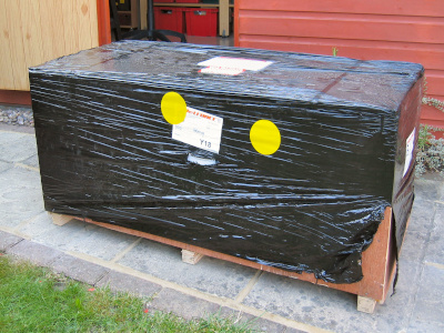

The crate is about 600mm square by 1200mm long, (1) I needed to get it up a step and through a standard door. Utilising old fashioned technology (levers and blocks) I raised the crate high enough to get a castored trolley (skate) under the crate which enabled me to position it facing the door. A mobile engine crane inside the workshop was then used to raise one end over the step, a bit of pushing and shoving and it was inside.
Once inside I removed the crate top and sides to check the contents. Usefully the swarf tray is bolted to the underside of the lid which means this can be removed and used to mark the holes in the bench without having to separate it from the lathe. I laid out the contents of the crate on the swarf tray, (2) all of the parts shown are wrapped and boxed but basically loose in the bottom of the crate. I assume that all of these extras are placed in the crate in the UK as I can′t imagine everything surviving a long sea voyage packed like this. The lathe had only a couple of scrapes on the paintwork where the swarf tray had rubbed on the back of the headstock. There were two small pots of touch-up paint in the box so the damage was easily put right.

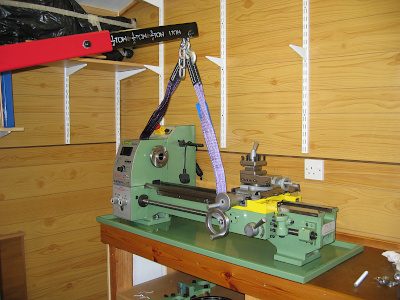
To get the lathe from floor to bench either needs three strong men or a crane. The crane makes it much easier. First of all I slung the lathe by passing a 1 tonne lifting strop under the headstock and between the sides of the mounting foot along the bed and up through the bed alongside one of the cross bracing. With the carriage as shown the lathe balanced quite nicely although tipped slightly forward. The manual says not to sling the lathe using the spindle, always a good idea to read the manual first, even if it is written in slightly Chinese English. Raise the lathe off the floor high enough to spin it through 90°, lower down onto the crane legs (3) where it just balanced and keep the tension on whilst manoeuvring the crane into the correct position. Note that the legs of the crane go under the bench.
Raise the lathe up to bench height and roll the crane forward gently. Lower carefully into position. (4) As it got nearer I put in one of the 12mm mounting studs to help position the headstock end, this gave me a free hand to position the tailstock. Whilst up in the air I put a block under the bed for safety and wiped the mounting feet. They didn′t feel too smooth so I put a thin piece of plastic under each foot to take up any imperfections. (I don′t know it this was a good idea or not, I havn′t seen it anywhere else, I used a piece of plastic DPC sheet cut to fit each foot)

Once in position to my liking (5) I bolted the lathe down to the bench. I suppose that a metal cabinet stand might have been a good choice but the bench has served well for a long time and is very sturdy. As can be seen by the different colour of the wood I have recently upgraded it with drawers and shelves. The bench top is from 40mm timber with 18mm chipboard screwed and glued to the top and the whole thing is very heavy. Three sections of 12mm studding with suitable nuts and washers secure the lathe very firmly and 300mm of 30mm x 12mm steel under the bench top at each end help to stop anything moving. I tightened the headstock end right down but the tailstock I left just pinched up.
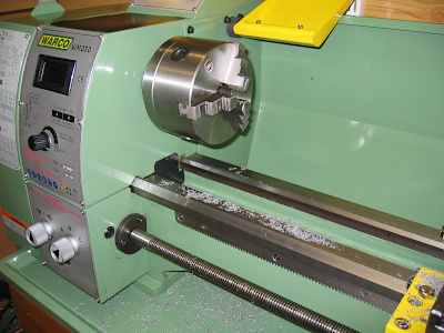
The lathe as delivered had surprisingly little grease on it and cleaned up very easily. All the bits that came off easily I removed and cleaned with WD40. Everything seemed in order so I carried out a quick test to see if parallel turning was the order of the day. I put a piece of hefty bar in the three jaw and left it sticking out about 150mm not supported by the tailstock. A couple of roughing cuts and some swarf in the tray, the first chip is in there somewhere (6) and then two passes with a fine feed along the bar. Result - headstock end 18.431mm tailstock end 18.445mm a difference of 0.014mm (0.0006") and the right way round. That will do nicely!
Now that the lathe is installed I will have to find out how it works. I have new tipped tools to try that I have never used before and will have to go over the whole thing carefully to see what can be improved.
There is a more detailed description of the WM250 and review on the following pages, starting with the headstock:-