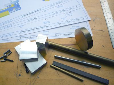
Elmer′s Metric Standby (No.19) Engine
Elmer Verberg designed and made many small engines and there are construction articles aplenty on the interweb. These small engines are ideal beginner projects and can be run on air or steam, I think that most are run on air and mine will also be powered this way. This is my version of one of his simpler engines - The Standby - also referred to as the 19 because this was the chapter number in Elmer′s book. The original is very small, about 2¼" long by 1½" high and designed with imperial measurements. My version is about 1.5 times larger (so I can see it) and designed with metric dimensions. I have redrawn the plans which are now on four A4 sheets (as a PDF below). The original plans were available from John Tomlinson's site but seem to have now disappeared. I have located all the Elmer's Engine plans and they are available from the download section. The Original Plan for the No. 19 engine should you wish to compare .

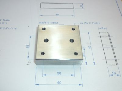
Foot
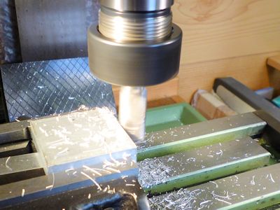
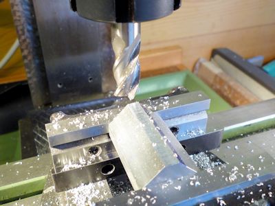
Starting from the bottom as it were, the first part to make is the foot. This is just a 40mm square of 10mm thick aluminium alloy. 6082-T6 grade is readily obtainable as a suitably sized (40mm x 10mm) extrusion and machines quite well. Starting from 40mm bar stock cut a length 40mm plus a little for machining. Make sure the milling vice jaw is parallel to the table and set the blank to mill one end square (3). Turn through 180° and machine to length.
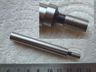
You may like to mark out and centre-pop the holes before mounting the foot in the mill vice. I didn′t on this occasion but it does give you a useful visual guide to check that you have wound the handle the correct number of times. Find the front edge, I use the gizmo shown at (4) above, which I find to be quick and accurate. Move the table Y-axis so that the spindle axis is on the centre line for the two nearest holes. If you use an edge finder like mine the amount to wind the handle is half the diameter of the finder plus 6mm. Lock the Y-axis and repeat from one end to locate the centre of the first hole.
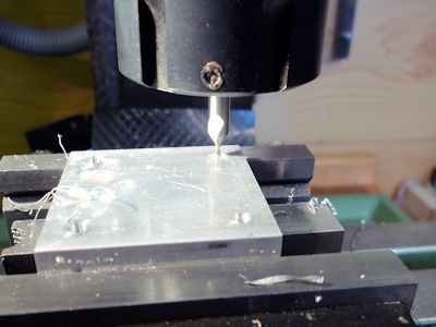
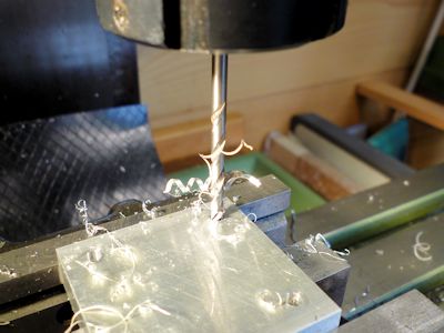
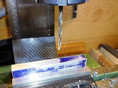
Centre drill (5) and then drill through with a Ø3mm drill (6). Move the table in the X-axis, 28mm, to position the next hole and drill as before. If you havn′t got a DRO it′s a matter of counting turns of the handle to set the position. Of course if you have CNC you have already finished! When positioning the holes make sure to always come at them from the same direction to avoid any backlash problems. By now you know the drill (sorry) move the table in the Y-axis 28mm, drill (5) & (6), then in the X-axis 28mm to find the last hole. I changed the drill from a centre drill to Ø3mm at each hole you could of course go round twice, centre first and drill second. It would probably be OK to do without the centre drill if you have stub twist drills. It is just that the longer drills can sometimes wander off centre when starting.
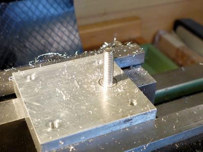
If you are happy with the co-ordinate drilling system outlined above you can just carry on and repeat the process for the two frame securing bolt holes. If you want to double check find the front edge afresh and then set the spindle axis on the centre line. Find the first hole centre and drill Ø4mm. Change the drill for either a suitable counterbore or use a 7mm end mill to machine (7) the counterbore 4.2mm deep. Before moving on the the next hole check that the counterbore is deep enough for the screw head (8).
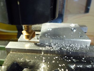
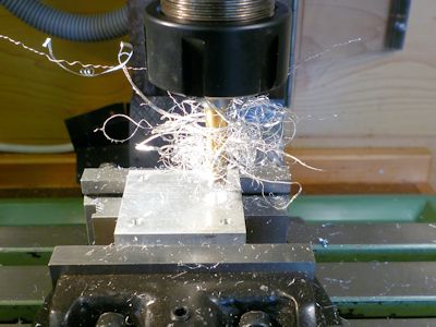
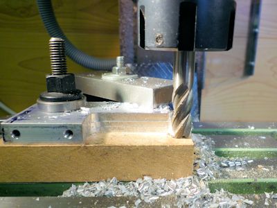
The last operation is to create the small chamfer on the top edge of the foot. There are a few options here: you could file it by hand, set the foot in the vice at 45° and mill each edge or use an angled milling cutter. I tried a bit of an experiment that seems to have worked OK, not sure if it is an approved procedure! I had a 90° countersink bit that seemed fairly robust so I reasoned that it would only be taking a small cut. I set it up and gingerly tried a small cut which worked OK so I tried it full depth (9). I left the cut at the required depth and turned the foot in the vice for each new corner. Strangely it seemed to produce a better finish when climb milling. The size of the chamfer is not critical: big enough to look as though you mean it but not too big to detract from the appearance (10).
As you can tell I use the ER25 chuck all the time on the mill, it is more accurate than an ordinary drill chuck but not quite as quick to use. It does of course avoid changing chucks which does save some time. To make it slightly easier to use I invested in a couple of ball bearing nuts (11), one for the mill and one for the lathe. They make closing the collets a bit easier especially when you are at the wrong end of the size range and need to apply a bit more oomph!
Frame
Machining the main frame is started in much the same manner as for the foot. Cut a length of 40mm x 10mm bar to just over 80mm long and square off the ends in the mill. I marked this part out (12) to avoid any errors as there are a few more holes to get in the wrong place. I use a permanent marker pen, quicker and easier than a bottle of marking out blue and a brush.
Drilling holes in the frame follows the same co-ordinate drilling method as for the foot and it is easier to drill the holes before milling the frame to shape. There are four counterbored holes for the cylinder mounting screws and two M2.5 x 8mm deep holes for the air inlet pipe bracket. The last hole from the face is the Ø10mm hole for the bearing (13). This could be reamed to ensure a good size but the bearing can be turned to fit if the drilled hole is slightly oversized, drilling in stages will probably result in a well sized hole.
The next two holes are Ø3.3mm tapping size for M4 in the bottom edge, to fit the cap-screws that fix the frame to the foot. When setting up make sure you are drilling at the correct end (furthest from the cylinder). Set the foot in the vice as (14) find the front edge and centre the drill in the Y-axis, find the end and set the X-axis for the first hole drill 10mm deep. Move in the X-axis for the second hole and drill.
At this point I have to confess to a slight design change brought about by breaking a 2mm tap in the frame. I tried everything to remove the tap including dissolving it using alum but no joy, believe it or not this is the first tap I have ever broken, still you have to start somewhere! It was only the securing hole for the air pipe bracket and I could have got away by putting a false screw in with Loctite but I decided to remake the part. This allowed me to correct a bit of a design flaw by making the frame 5mm longer to give the blanking plug something to fix into. As a consequence some of the photos show the original frame but the text refers to the new frame and dimensions.
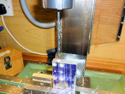
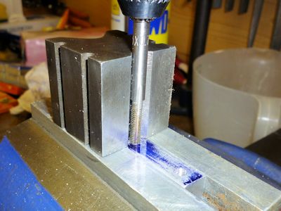
The next hole is probably the single most important in the engine and the first time I tried it it drifted off line slightly, the second go in the modified frame worked despite being 5mm deeper! Carefully set the frame upright in both planes, then lock the X and Y. Start with a centre drill. Then drill Ø3mm as deep as you can with a standard drill. Change to a long reach drill (15) and finish to meet the bearing hole. Withdraw the drill frequently to clear the swarf. Photo (16) shows the finished hole which is 63mm deep and the last hole in the frame the 3mm air passage from the cylinder to join with the deep hole just drilled.
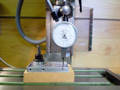
There are a couple of ways to form the "L" shape of the frame. Drill a hole then saw and file out the surplus, mount the frame vertically in the vice and use a ball nose cutter in the mill or mount the part flat on the mill table as I did. Set the frame on a piece of flat wood, MDF is good as it is flat and smooth. Clamp down using the 10mm hole and set the front edge parallel to the table using a DTI (17). Once aligned add another clamp and tighten down. Use a 10mm end mill to remove the surplus material (18) which will also give the correct radius in the corner.
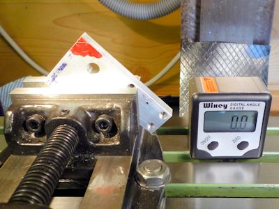
Remove the corner of the frame by setting in the vice at 45°. I used the digital angle gauge shown in (19), just set the gauge to zero on the table and then hold it against the edge to set the job in the mill vice. If you are using it on steel it will hold itself in place with inbuilt magnets. Mill the corner down to the marked line, not a critical measurement. The two small chamfers on the cylinder end of the frame I made using a countersink bit as for the foot.
That should be all the mill work done on the frame and it just remains to tap the holes. I just set the part in the bench vice level with the top of the jaws and used the angle block to keep the tap vertical (20). For the smaller tapped holes I used a purpose made block to keep the tap vertical but still managed to break a 2mm tap. With the remake I made the holes M2.5 and managed to tap these without a problem. As you can see the vice jaws are aluminium and get re-machined from time to time to keep them flat square and clean.
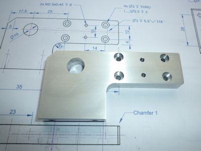
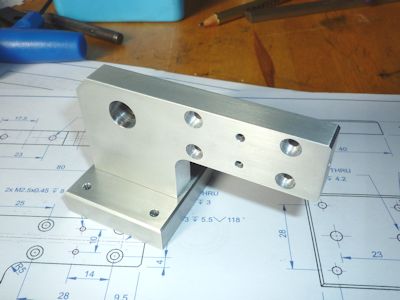
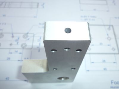
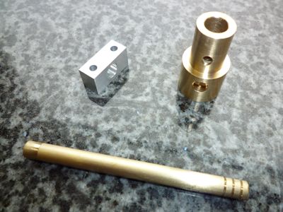
The finished parts above (21) & (22) could benefit from some more cleaning up. I don′t like highly polished finishes but a good satin finish is almost as difficult to obtain and still shows greasy fingerprints. A small brass blanking plug needs to be made to seal off the open end of the air passage through the frame. This is just a short length of Ø6mm rod turned down to Ø3mm to fit in the hole, chamfer the ends and put away safely until assembly time.
Cylinder
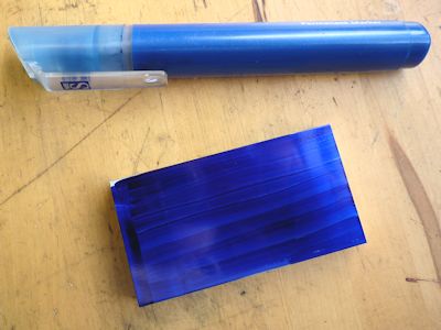
Now that the frame is finished we have something to hang the other parts on and the next part I made was the cylinder. This is a slight deviation from the original as it is made from 20mm square aluminium bar stock. Cut a suitable length but allow an extra 5mm for final machining to size. The cylinder could be machined on the lathe holding the blank in a four jaw chuck but I thought I would try using the mill.
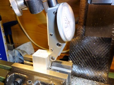
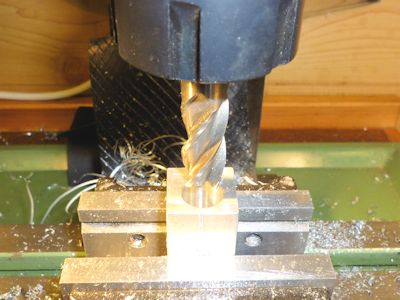
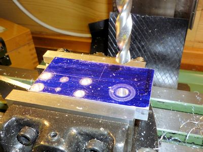
Clean and square up one end in the mill. Invert the blank and set accurately vertical in the vice (23) clean off the top but don′t bring to length yet. Use a series of drills and mills to create the bore. I used in order: a centre drill, an 8mm twist drill, a 10mm slot drill, a 12mm endmill and finally a 14mm endmill. I used the slot drill to make sure that the bottom of the hole was flat as endmills leave a domed effect and of course don′t cut in the centre. Withdraw the cutter frequently to get rid of the swarf as this is quite a deep hole and may even be deeper than the flutes on some cutters. My little WM14 mill has a digital readout on the quill so I used this to get the required depth. I put an old rule flat on top of the block, brought the tool down just to touch it and zeroed the reading. Then drilled / milled (24) slowly down to a depth just greater than required.
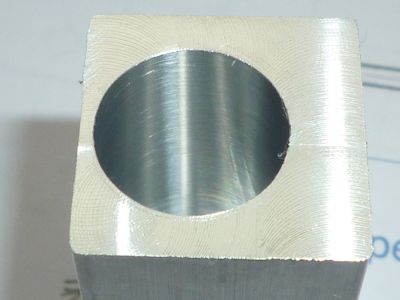
Once the drilling / milling is complete you end up with a block a little longer than required with a nice hole in it (25). I was expecting either to use a boring bar in the mill or to do a lot of honeing but the finish was surprisingly good. Carefully measure the depth of the bore and mill the open end to bring the bore to the right depth. It is much easier to mill the outside to length rather than trying to bore exactly to depth (I think). Mill the other end of the cylinder block to give the required finished length. The last operation in the mill is to use the co-ordinate drilling system to put in the tapping holes for the four securing bolts and the one through hole for the air passage. The most important thing is not to drill the fixing holes too deep otherwise they will break through into the cylinder bore and it′s start again time. What I should of done when the part was still set in the mill was to machine the chamfer round the rim with a boring bar but I removed the part too soon and will now have to machine the chamfer in the lathe.
To remove the outer corners of the cylinder mark a line 4mm from the outer edge, you can just make out the blue in the photo. Set the piece cross-wise in the vice (26) on a couple of parallels to set the height, use the angle gauge or protractor to set the 45° angle. Mill down to the line noting the Z-axis reading. Flip the piece to the other corner setting on the parallels to keep the height and make sure the angle is set. Now mill down to the same setting of the Z-axis and all being well both sides should be the same.
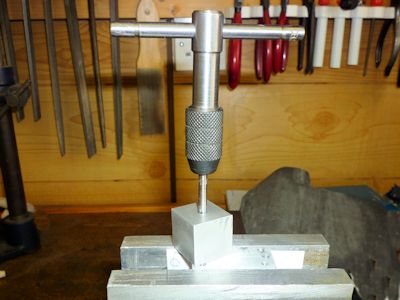
Tap the four M3 holes for the mounting bolts, a tapping and staking tool would be ideal but a simple block with a hole to suit the tap will do the job (27) reasonably easily. You might need quite a collection of tapping blocks though, I think every tap I have has a different diameter shaft.
It would have been much easier if I had remembered to do this in the mill. It took much longer to set up than it did to cut the chamfer (28) using a boring bar in the lathe with the top slide set over. It took almost as long to get the lathe back to "normal" mode afterwards. One thing to be careful of is not to overtighten the four-jaw otherwise you could end up with an oval cylinder bore, note the bits of card to protect the finish.
Bearing & Inlet Pipe
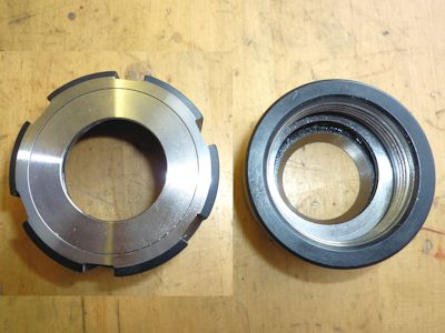
The main bearing together with the crankshaft also serves as the inlet and exhaust valve. The bearing is turned from brass and I find it easier to work from the end of a stock bar and part off on completion.
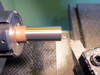
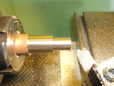
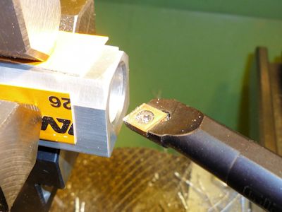
Set the stock bar in the chuck with at about 30mm protruding and turn the outer diameter down to Ø14mm (29). Turn the smaller diameter that fits into the frame down to Ø10mm for a length of 13mm (30). Use a lathe tool with a minimum radius tip to create a sharp corner to the shoulder.
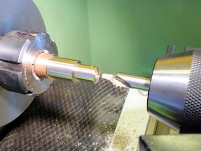
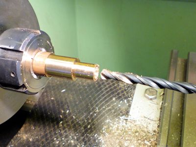
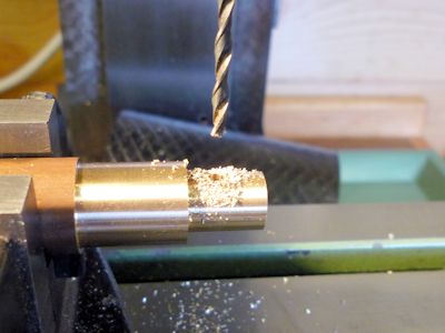
The bearing hole needs to fit the crankshaft and my intention was to use a bit of stock 6mm stainless bar, this turned out to be 5.96mm and a reamed hole was too loose. Rather than turn the shaft from larger stock I experimented and found that a 15/64" drill would produce a well fitting hole provided I drilled carefully in stages up to the finished size and being in brass the finish was pretty good. So start with a centre drill (31) and then work up slowly to the finished size (32). You could equally well (probably better) ream this hole to size if you are going to turn the crankshaft to size or have a rod that is nearer 6mm than mine was. You could use silver steel (drill rod) for the crankshaft and then the size would be 6mm.
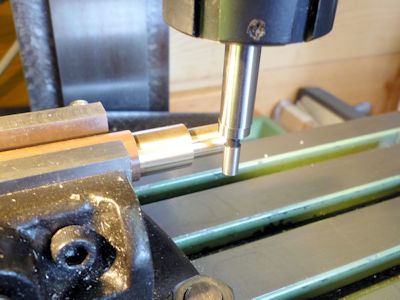
It is easier to leave the bearing on the stock bar as it gives something to hold onto in the milling vice. Set the bar level and find the centre (33), find the end and move to the hole location. Centre drill and drill Ø2.5mm (34) for the inlet port hole, a small countersink on this hole (35) will sort out any misalignment problems with the long hole that runs through the frame.
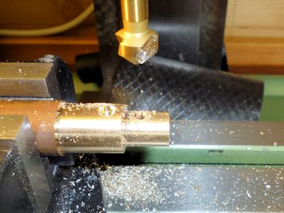
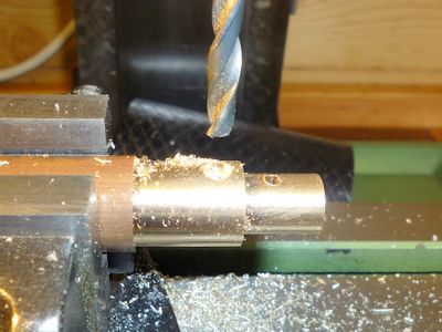
The air inlet pipe is fitted into a counter-drilled hole in the larger end of the bearing. The exact size of the counter-drill will depend on the size of the pipe. I found a short length of brass pipe about 5mm diameter but it wasn′t particularly round so I skimmed one end in the lathe the final diameter was 4.7mm. Move to the centre of the inlet pipe and drill through Ø2.5mm then counter-drill to suit the inlet pipe (36) to a depth of 3mm.
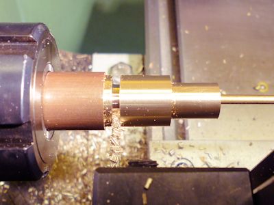
Return the bar to the lathe and part off the bearing (37), I left it a little long so that I could face it to length as the parted finish is usually a bit rough. The thin rod on the left is just a piece held in the tailstock chuck, it stops the parted off bit falling onto the lathe or in amongst the swarf. The pipe needs no real explanation, use what is to hand (38). Copper pipe will likely be smaller for the same bore so adjust the bearing counter-drill to suit. The bit I found has quite a thick wall, not sure what it was for originally but had spiral extrusion marks along it′s length before I cleaned it up a bit. I added some grooves on the outer end and you can see the other end is turned down to make it round. The pipe bracket is the final part in this section and is simply a small block of aluminium with a hole to suit the pipe and two Ø2.5mm holes to bolt it to the frame.