Warco WM 250 Lathe - Review Part 2
Continuing a detailed look at the lathe, this section covers the bed, carriage and top-slide. I have been using the lathe quite a bit so I hope you will ignore the swarf in some of the photos.
The Bed
A one piece substantial iron casting. The top surface of the bed is nicely ground and has two prismatic guides (1). The front guide for the carriage and the rear guide locates the tailstock. The two sides of the bed are braced by substantial cast in cross webs (2). A label at the end of the bed states that the slideways are induction hardened, I am not sure just how hard this surface is though and I have no means of testing it (save taking a file to it). The rack for the carriage handwheel is fitted to the front of the bed in two sections using socket head screws and roll pins for location, the join is not evident when traversing.
Induction Hardening - A widely used process for the surface hardening of steel (also gray cast iron apparently). The components are heated by means of an alternating magnetic field to a temperature within or above the transformation range followed by immediate quenching. The core of the component remains unaffected by the treatment and its physical properties are those of the material from which it was machined.
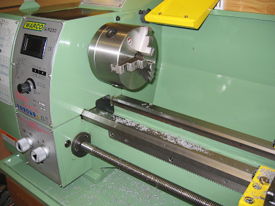
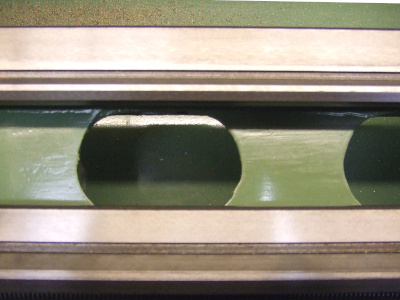
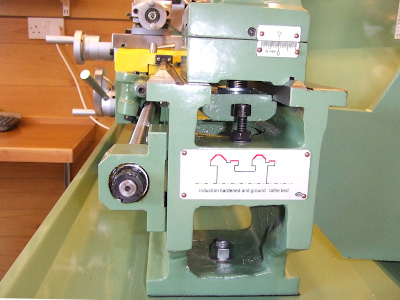
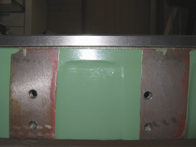
As may be seen from the end on view (3) the tailstock guide is much smaller than the saddle guide. The groove between the prismatic sections and the flat part of the bed is not ground and there is a noticeably rough and sharp edge to both grooves. I carefully removed the sharp corners with a slipstone. The mounting feet are cast integral to the bed and have three mounting holes all on the centre line, two at the headstock end and one at the tailstock. The paint finish on the bed is reasonable but I suspect that there is a good deal of filler in places. I also noticed that the rear of the bed casting carries two machined pads with threaded holes to take a bolt on milling head which is available as an extra (4). I can′t think of an immediate use for these so they will require painting to prevent rusting.
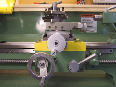
The carriage (5) has two main sections, the saddle, guided by the front and larger of the two prismatic ways and the apron which is held in place by four allen headed bolts, there are no dowel pins or other means of alignment that I can see. The saddle is kept in place on the bed by a full length gib strip at the rear. I found that all the screws on this were loose and the saddle was therefore free to move up and down. The front is restrained by two L-shaped assemblies which bolt to the underside of the saddle and hook under the front of the bed. The right hand retainer also serves as the saddle clamp which is not very effective. (See Saddle Clamp Lever for a better solution). There are no gib strips at the front presumably because in normal use the front of the saddle will be pressed down onto the bed.
The apron carries the saddle handwheel at the lower left, the half-nut engagement lever on the right and the screw-cutting engagement dial on the right hand edge. The saddle handwheel being on the left means your hand is closer to the hot chips than if it were on the right but it does though have a friction dial which I have already found to be very useful when turning up to a shoulder. A minor criticism is that the saddle handwheel and cross-slide handwheel are in close proximity and it is quite easy to nudge one whilst using the other.
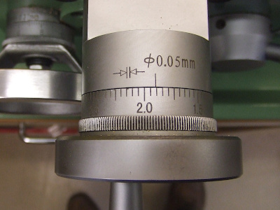
The cross-slide handwheel is fitted with a nicely engraved friction dial, as may be seen from the photo (6) the divisions are 0.05mm. This though is not a true reading as it refers to the diameter (Ø) . That is to say, winding the slide in by 0.10mm will actually take a cut of only 0.05mm. My last lathe had a "proper" dial that indicated the cross-slide movement so it is a matter of getting used to it. I have read that some owners of this lathe have made a direct reading version to replace this dial. (I have got used to this now and find it quite easy to work with.)
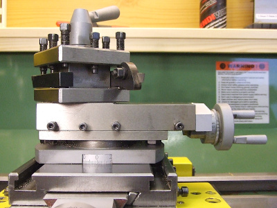
The top-slide is mounted to the cross-slide by means of a substantial clamping plate. (7) A close look at the photo shows that the plate has flexed in the centre where the cutout for the angle scale has been machined. This clamping plate has been widely reported as a source of vibration in the 9x20 series of lathes to which the WM250 would appear to be related. I cannot say I have encountered any such problem thus far but the clamping bolts are a bit of a pain, being hidden in a relatively small gap beneath the top-slide. I have seen an article in Engineering in Miniature (Tee Publications) describing a fix for this. The lathe is supplied with a four way toolpost as standard, originally fitted with a hefty detent spring which I removed. I feel a quick change toolpost coming on! (See Quick Change Toolpost which covers both a new cross-slide toolpost and fitting a QCTP).
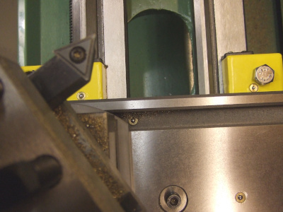
The T-slots in the top-slide mean that this can be used as a machine table in conjunction with the bolt-on milling head. It is of course useful for additional tool holding arrangements such as a rear toolpost. The locating pin for the top-slide could also be removed allowing it to be positioned anywhere on the cross-slide. This may be useful as the cross-slide movement is limited to 115mm which is less than the 125mm which it needs to be for maximum facing capacity. Photo (8) shows another slight shortcoming, the cap head screw that retains the cross-feed nut is proud of the surface, as is the oiler, which means that the table surface is not flat if you want to use it for milling. The oiler for the dovetail slide is also cunningly hidden at the bottom of the T-slot just where all the swarf collects and is difficult to clean out due to the clamp plate above. The BZP hex headed bolt on the right I have added to prevent the threaded hole for mounting the traveling steady filling with swarf.
The review continues with a more detailed look at the tailstock and accessories:-
