Lathe Saddle Clamp
This is a little project I did some time ago and I have found the modification to be quite useful. It is based on a series of articles in Engineering in Miniature from July 2007 written by Anthony Mount. I have made a couple of changes to the original and later changed the design of the clamp. Both the original and altered clamping methods are shown below.
As supplied the WM250 along with many of it′s "Chiwanese" stable mates has a rudimentary saddle clamp operated by an allen key. The original clamp is part of the saddle guide block and it′s design is not well thought out, or to put it another way - it doesn′t work!
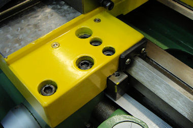

Photo (1) is a view of the top of the saddle as the clamp and guide block is being removed. The two screws at the front hold the apron in place and the line of three holes nearer the bed are for the cap screws that hold the clamp and guide in place. The leftmost screw is M8 and the other two screws are M5. The M8 screw for the saddle clamp is very close to the cross-slide and at certain settings the cross-slide gib adjustment screws cover the saddle clamp so that it is impossible to insert an allen key. Removing the clamp and guide block is straightforward, just undo the three screws but put something under the block to support it because it can fall behind the apron and get wedged in amongst the half nuts and lead screw!
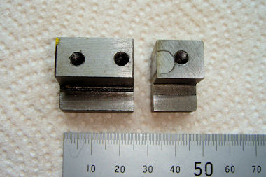
The clamp and guide block removed from a similar lathe (2) this is much better machined than the block from my lathe and the saw cut is centred between the M8 and M5 threaded holes. The saw cut is intended to let the clamp block flex upwards but the remaining web is much too solid to allow any bending. To overcome this shortfall you may find that the two smaller screws are left loose so that the M8 screw can pull the block up under the lathe bed to provide the clamping force, not an altogether satisfactory arrangement.
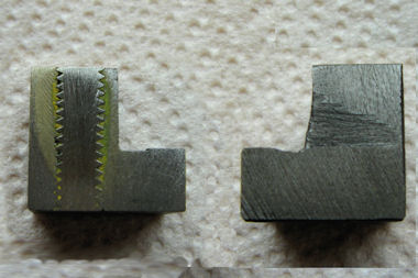
The modification is to split this block into 2 pieces by continuing the saw cut so that each part can perform it′s own function. Fortunately the three holes are at equal centres so the re-machining needed is minimal. The sizes of the two parts are dependant on the position of the original saw cut which appears to have been put in, somewhat arbitrarily, by hand. The cut in the block from my lathe (3) was much closer to the 5mm threaded hole meaning that the smaller clamping block required more machining to fit neatly under the saddle. The M8 hole will also need to be filled with a length of studding or a bolt loctited in as the original M8 cap screw will no longer be used. In photo (4) you can see the poor quality of the machining on the block. The right hand part is the original shape which is now the guide block the remains of the saw cut can still be seen and the left hand part I have squared up to form the clamp block. Because the original saw cut was close to the M5 hole this has had the effect of pushing the guide block to the right (as you stand in front of the lathe) and the clamp block consequently sticks out to the right of the saddle by about 5mm. I have machined this 5mm off so that the clamp block is level with the side of the saddle which is why so much of the stud filling the M8 hole can be seen.
The saddle guide section can be fitted back to the lathe now using the two leftmost holes in the saddle 8mm on the left and a 5mm in the centre. The choice in refitting the guide block is either to drill out the block and tap 8mm for the leftmost screw or to make a small collar to take a 5mm cap screw. I followed the original article and made a small collar for a 5mm cap screw.
The re-machined clamp is inserted and held in place under the saddle tight against the guide block and the front of the bed. The centre for the M5 clamp screw can now be marked. The new hole can then be drilled and tapped to take the clamp screw. Depending on the position of the saw cut this may be nearer the centre than mine was. The original article had the new M5 clamp thread going almost down the centre of the glued in stud.

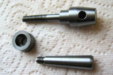
The next job is to make the clamping screw and lever, this is fairly straightforward turning and the drawing (5) I hope is self explanatory (Click on the image for a readable version). The original article shows the clamping screw with a head similar to mine but with a large washer under it bearing on the top of the saddle. I didn′t like this as it overhung the edge of the saddle somewhat. I made mine similar in shape to a cap screw with the head added on top, this means that screw tightens in the original counterbore rather than on the top of the saddle which saves the paint. There is a space between the head of the clamping screw and the top of the saddle and it may be worthwhile checking the depth of the counterbore to ensure that this happens. Photo (6) shows the clamp screw, handle and the spacing collar to reduce the M8 counterbore to M5 (Note there is no drawing for the spacer, just measure and make to fit). If you do not want to make the handle a ready made bristol lever could probably be found to suit.
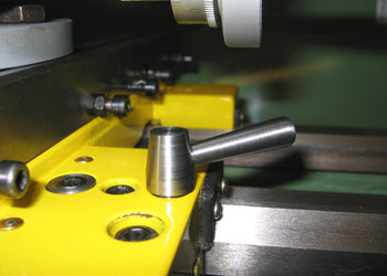
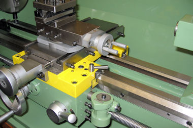
Photo (7) shows the finished article fitted to the lathe. You can see the spacing collar on the left hand side. I could have made the handle a little longer but it would have hit the cross slide, as it is, it can spin all the way around. Once fitted I adjusted the angle of the handle when tight by shaving a little off the shoulder of the cap screw part of the clamping bolt. Photo (8) Is a wider view of the finished clamping bolt and the ′L′ shaped clamping block can be seen now painted yellow to match the saddle. It certainly works but doesn′t really lock the saddle as tight as it could be this is because the clamping block tends to tilt (front to back) as it tightens. Also it is possible for the tailstock to collide with the handle when the clamp is unlocked.
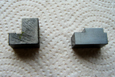
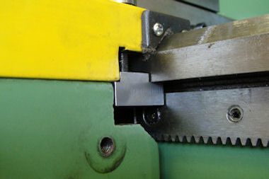
After using this for some time I decided to try and make the clamping a bit more solid. I noticed that there was a small ledge inline with the bed where the saddle and apron meet. I measured up and made the new clamp shown in photo (9) alongside the old clamp. The only difficult bit is to get the clamping face to fit level and without gaps to the underside of the bed. I used a feeler gauge and took shavings off of the step that hooks under the saddle until it was a good fit. The clamping is now much better and fairly light pressure on the clamping handle will stop the saddle moving. Photo (10) shows the block in place, I have removed the screwcutting dial to enable a clear view.
Whilst rumaging about under the saddle with feeler gauges it is a good idea to check the clearance between the guide block and the underside of the bed. I found that there was too much clearance for my liking and reduced this to give a better fit and stop the saddle lifting. Mine was a small enough amount to remove by rubbing on wet & dry paper on a flat surface. There is another guide block at the left side of the saddle and this can be treated in a similar fashion. Don′t take too much off though or the saddle will become difficult to move along the bed! The guide at the rear of the saddle has an adjustable gib so this is easily tightened if necessary.