Cam Operated Tailstock
To clamp up the tailstock on the older WM 250 you need to use a spanner. This works well but means that you always need a spanner to hand, you can just guarantee that it is the other side of the workshop. The spanner collides with the topslide so you can only make a quarter turn and if you don′t slacken the nut a full turn the clamp will jam as you try to slide the tailstock along the bed. Later versions have a lever and cam operated tailstock clamp.
This is a modification to the WM 250 that I have been meaning to do since I first got the lathe. It is based on a series of articles that appeared in Engineering in Miniature (June - August 2007). The modification (1) involves some machining to the tailstock casting and probably shouldn′t be carried out if you are worried about damaging your pristine paintwork or voiding a guarantee!
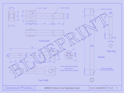
I have included some drawings (2), usual disclaimer - check that the measurements are right for your lathe. The two main components involve reducing the diameter of stock bar some 100mm long so you may want to use a centre in the tailstock for support, this means you have to do all the turning before dismantling the tailstock.
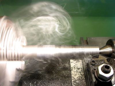
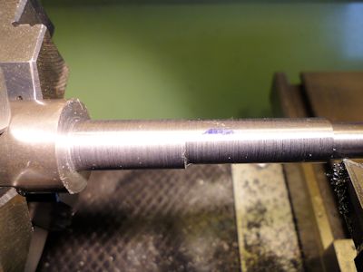
The first part I made was the clamp bolt. Chuck a length of 25mm stock bar in the three jaw and face and centre drill. Set the bar out from the chuck to allow turning a 67mm length (3) amazing just how much smoke you can get from just a little cutting oil.
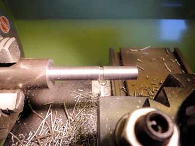
Give tailstock support if you wish, although this part is probably sturdy enough to turn without any additional support. Turn down to 12mm diameter for the full 67mm length leaving a square shoulder. Use a parting tool to make a 3mm wide groove (4) for runout space when cutting the thread, the groove needs to be about 1.5mm deep (thread pitch x 0.8).
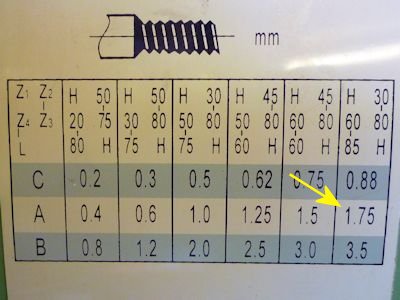
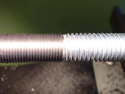
Next up is to cut the 12mm x 1.75 thread, you could use a die if you are feeling fit but the lathe is designed to do this job. I haven't done a lot of screw-cutting on the lathe and this particular thread had a bit of a steep learning curve. Lesson 1, don′t believe all you read, particularly the change gear chart on the lathe headstock (5). First time round I got a thread that was too fine a pitch (6), my thread on the left and a bit of 12mm studding (allthread) on the right. I rechecked all the change gears and made sure the selector on the gearbox was on the right letter but everything was as per the chart. So I set to with the calculator to work out what the gears should be.
Change Gears & Screw-Cutting on on the WM 250
A brief diversion trying to understand how the change gears work! The spindle has a 40 tooth gear machined in place so everything has to start from there to achieve the correct ratio between spindle and leadscrew. If the leadscrew rotates at the same speed as the spindle it will cut a thread of 1 x the leadscrew pitch. Likewise if the leadscrew rotates at half the spindle speed the pitch will be 0.5 x the leadscrew pitch.
The leadscrew pitch on the metric WM 250 lathe is 3mm, this can effectively be altered by the gearbox to give:- Position A - 3mm (pitch x 1), Position B - 6mm (pitch x 2), Position C - 1.5mm (pitch x 0.5)
From the above to get the required 1.75mm pitch for an M12 thread the ratio between spindle and leadscrew needs to be 1.75/3 or 0.58333
The headstock chart takes for granted that the first gear is always 40 tooth (the spindle) and this is not shown on the chart. The chart also shows H in two places this indicates a spacer, why H? I have no idea. The chart shows for 1.75 pitch the following:-
H 30
60 80
85 H
The ratios work out like this:-Spindle 40 which meshes with 30 giving a first ratio of 40/30 or 1.33333
The 30 also meshes with the 80 to give a second ratio of 30/80 or 0.375
The 60 is fixed to the 80 and meshes with the 85 to give the third ratio of 60/85 or 0.70588
Multiply the three ratios together 1.33333 x 0.375 x 0.70588 = 0.35294
So for every 1 revolution of the leadscrew it will move the carriage the leadscrew pitch which is 3 x 0.35294 = 1.05 this is not the 1.75 required!
It took me a little time to grasp this but the gear between the spindle and the next gear in the train is effectively just an idler. It doesn′t change the overall ratio so you can just ignore it and go from 40 to 80 in this case giving just two ratios to work with namely 0.5 and 0.70588 which when multiplied together give the same overall ratio 0.35294. Probably safer to use all the ratios as you can′t ignore anything with a five gear setup.
So a different overall ratio is required. The first two ratios on the chart multiplied together give a ratio of 0.5 so I started there and worked back. My maths is rather rusty but I ended up with 0.5 x ? = 1.75/3 or 0.5 x ? = 0.58333. Rearrange and ? = 0.58333/0.5 which = 1.16667 this is the third ratio. (I assume working to 5 decimal places is near enough, many of the ratios come out as recurring decimals.) So a bit of trial and error with a calculator using the gears provided with the lathe, the pair that gives this is 70/60. So the chart should read:-
H 30
70 80
60 H
I did a sketch of the final solution which I hope makes things a little clearer. This is the set of gears I used and as it worked I assume my calculations were correct or thereabouts... I have checked the other metric pitches in the table and these are correct. I don′t know if the table has been amended on later models of the lathe and I haven't checked any of the imperial setups.
Right, back to the project albeit briefly.
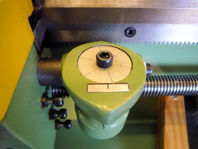
Having sorted out and set up the right gears it was time for Lesson 2, You can′t use the threading dial (7) for all threads even if they are metric on a metric lathe. It turns out that the dial will only work for certain pitches and I know this because... Having done a bit of reading I find that this is due to the ratio between the leadscrew and the threading indicator gear wheel.
Another brief diversion: The screw-cutting thread indicator dial meshes with the leadscrew via a 30 tooth gear. To get the indicator dial to rotate once the carriage has to move 90mm (number of teeth x leadscrew pitch). Only those metric pitches that divide exactly into 90 will be able to use the dial when screw-cutting. Thus pitches of:-
0.5, 0.6, 1.0, 1.25, 1.5, 2.0, 2.5 and 3 will work, pitches of 0.7, 0.8 and 1.75 won′t work.
Replacing the 30 tooth gear with a 28 tooth gear would work for the missing pitches but not for all. With a 28 tooth gear the
carriage has to move 84mm for a full turn of the indicator and 84 is divisible by 0.7, 0.8, and 1.75. So either change the gear, make an indicator that has both gears or just leave the leadscrew engaged and reverse the lathe.
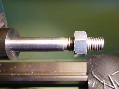
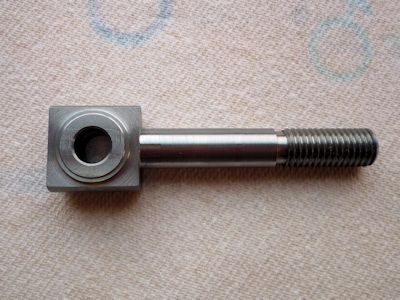
Finally I was able to cut the thread by keeping the leadscrew half-nuts engaged all the time. This wasn′t too difficult, just a matter of keeping to the sequence - put on cut, start lathe, cut thread, stop lathe in the runout, retract tool, reverse lathe and run tool back to start, return tool to last cut depth, switch lathe to forward direction, put on cut etc.. Once the thread was cut I ran a die along it to correct any minor discrepancies in the thread form. The final result can be seen at (8) with a 12mm nut screwed on just to prove it works.
Once the thread is complete put a chamfer on the end and then either part off to length from the stock bar or use the band saw. Reverse in the lathe holding the 12mm shaft and face the bolt head to length.
To machine the head of the clamp bolt I used the mill vice to hold the shaft of the bolt with the head out to one side as shown (9). I supported the bolt shaft parallel to the table on a section of square bar, I could of used the V slot in the vice jaw but this tends to leave marks. Bring the cutter down just to touch the top surface of the bolt head and then remove 4.5mm, I took several cuts as my clamping method is not the firmest. Flip the bolt over and set the just machined face parallel to the table, I used a packing piece and feeler gauges. Once set up, find the top and remove 4.5mm from this side, this should leave the bolt head 16mm thick. Leave the bolt clamped in the vice
Find the centre of the flat face and drill through 10mm (10). I used an edge finder to locate the centre, touch to locate the front side then wind out the Y slide half the diameter of the bolt head + half the diameter of the edge finder. Repeat this from the end to find the centre in the X direction. Use a spotting drill or centre drill to start off. I don′t have any large reamers so the hole needs to be drilled as near diameter as possible. Do it in stages so the final drill has to take off as little as possible as drills tend to cut oversize if doing the whole cut in one go.
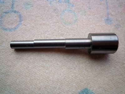
To turn the bosses on the clamp bolt needs some form of mandrel to hold the bolt (11). You could use an expanding mandrel if you have one or make a short stub mandrel. I had a rummage in the box of useful bits and found a mandrel I had used for a previous job it needed a few extra washers but it doesn′t have to be pretty. You could just use a bit of studding and a couple of nuts. Having checked carefully that the rotating bolt shaft misses everything turn down to diameter. I was going to leave the bolt without the bosses but these are necessary to provide clearance for the pocket corners. The finished item is shown at (12) you will notice I have an extra step in the boss, a momentary lapse of concentration but I made both sides the same, it makes no difference to the operation and once installed you can′t see it.
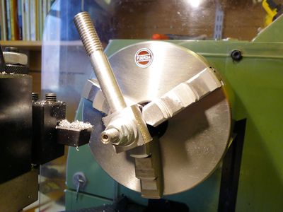
The cam shaft is straightforward turning but is longer and thinner than the bolt so tailstock support is useful here. Turn down a 20mm stock bar to 12mm for a length of 83mm and then turn down to 9mm for a length of 25mm. Change to a four jaw independent chuck to turn down the 10mm cam section (13). To set up for turning the cam first centre the turned 12mm section then make sure that one set of jaws is horizontal. Wind in the tool to just touch the surface and zero the crossfeed dial. slacken the rear jaw and tighten the front jaw to move the bar over by 0.5mm tighten the chuck jaws. Check the eccentricity using the tool, touch one side turn the chuck through 180° and touch the tool again the difference should be 1mm. Once satisfied with the setup turn the cam section down to 10mm for a 33mm length the final cut should just blend with the 9mm section if the setup was right, as per the finished cam shaft in photo (14).
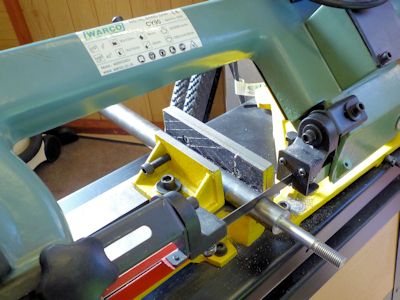
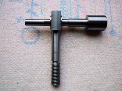
Once the cam section is turned remove the bar and change back to the three jaw chuck. Either part off the cam shaft to length or saw off (15) - the photo actually shows sawing off the clamp bolt - reverse in the chuck, face to length and add a nice chamfer. The drawing shows the hole for the handle but don′t add this yet wait until the final assembly when the hole position can be fine tuned to give the best operating angles for the handle. Photo (16) shows how the two parts fit together
Modifying The Tailstock Casting

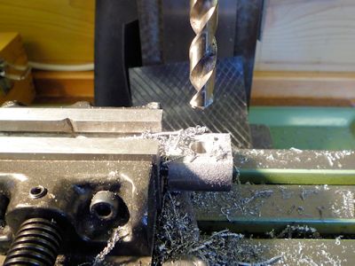
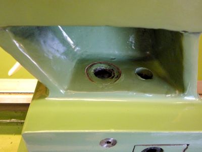
Now come the modifications to the tailstock casting, fortunately the cast iron is fairly easy to machine if somewhat messy. If you have a large mill you can probably do the machining without taking the barrel and handwheel off but I stripped mine right down to make space and make lighter. The hole for the cam shaft needs to be drilled from the rear of the casting so that the 9mm and 12mm holes are truly concentric (17). Half the battle is to mount the casting firmly and upright. A small angle plate at 90° to the table is used to hold the casting with the machined face vertical. There is a convenient hole to take a bolt or stud where the offset screw mechanism fits. I supported the weight of the casting on a strip of wood which also prevents drilling into the table. I marked out with a centre pop where I wanted the hole and centred up on this. Hole position is dependant on the casting thickness, nominally 12mm from the base, check that the large end of the camshaft does not foul the tailstock base casting otherwise it will be difficult to set the tailstock over should you need this function. Start with a spotting or centre drill then drill right through in stages to 9mm, then open up to 12mm to within 24mm of the front of the casting.
The drawing at (18) is a sketch based on my tailstock dimensions. Please check that everything fits before carving cast iron!
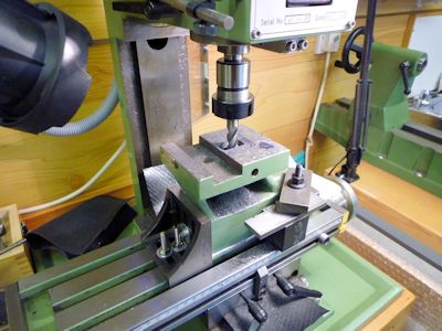
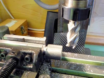
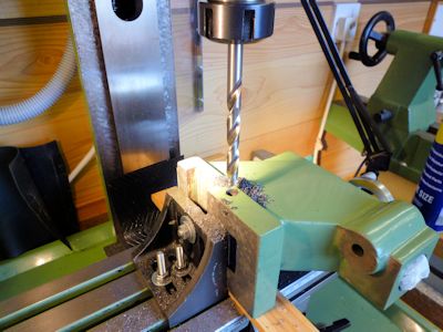
Remount the tailstock with the machined face upwards, I used the angle plate with a length of studding through where the barrel fits and an additional clamp on the square section of the tailstock. I had previously marked out where the pocket was required on my tailstock this left only a thin wall at one end of the pocket. The pocket is quite deep, 26mm, and really needed a long reach milling cutter or slot drill, either will do as there is already a large hole at the centre to allow for downfeed. The cutter needs to be 8mm diameter otherwise the corners will foul the clamp bolt. I did it in two stages using a larger mill to remove the bulk of the metal (19) and then cleaned out the corners with a 8mm slot drill. Do a trial assembly of the camshaft and clamp bolt whilst the casting is still bolted in place making sure the camshaft rotates freely and the clamp bolt can move up down and sideways in the pocket. If everything works unbolt and clean up.
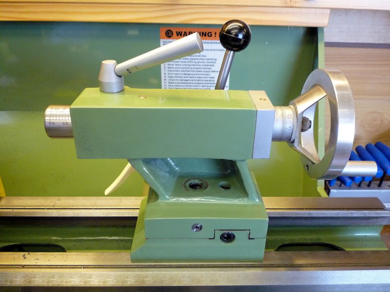
Reassemble the tailstock on the bed with the clamp in place and adjust the 12mm nut so that rotating the camshaft will lift the clamp bolt and plate to stop the tailstock sliding. Adjust until satisfied and mark the large end of the camshaft where to drill the hole for the operating handle, it needs to move through about 45° to achieve the necessary clamping force. The handle is a 10mm rod with a plastic ball on the upper end or you could machine something to match the existing machine handles. I just drilled a 10mm hole in the camshaft to take the handle and used Loctite to fix the handle in place. The handle could be threaded and the hole in the camshaft tapped if you prefer. The hole needs to be angled out at about 5° to give hand room and miss the tailstock handwheel. Photo (20) shows the tailstock once all is reassembled, you can just make out the top of the cam bolt. It looks a bit rough around the hole and it would probably be possible to disguise the holes with a plate, copious filler and paint, but I don′t think I will bother.
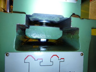
Once all is assembled you may still find that the tailstock doesn′t always slide freely and jams up. This is caused by the clamp plate swinging and digging in to the underside of the bed. This tendency can be cured by the addition of a spring between the clamp plate and the underside of the tailstock (21). You will also need a couple of large washers to stop the spring disappearing into the holes in the tailstock and clamp plate. The spring, if strong enough, will also hold the handle and stop it rotating. You may find that despite the spring the handle drops down. To stop this a small peg can be screwed into the tailstock casting (22) to support the handle.
This is an excellent upgrade and works very well. The principle could be applied to any of the similar Chinese lathes that come without a lever operated tailstock. I can foresee the nut working loose and loosing the clamping effect, I will find and fit a "Nyloc" nut soon, there is no room for a lock nut without remaking the clamp which could be another little job to make it a better fit and alleviate further the digging in problem.