Warco WM14 Milling Machine
Whilst having owned a lathe for many years I have never owned or used a milling machine. I know that many model engineers manage very well with just a lathe but I thought that a small milling machine would make life a little simpler. After much deliberation I settled on another of Warco's offerings, the WM14 vertical mill. This is the smallest of a series of similarly designed machines manufactured by Weiss Machinery Co. Ltd. based needless to say in Nanjing, China. The catalogue picture (1) and specification (2) are reproduced below.
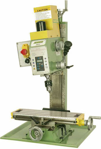
I suppose this would be classified as a mini-mill although it is very heavy and seems quite rigid in operation. I have tried taking what I think are quite heavy cuts and it doesn't complain. On arrival the mill was very clean with only the minimum of grease to be cleaned off. It is just a bit heavier than I could comfortably lift by myself but with the aid of a friend it was easily placed on the bench. The swarf tray is not standard unless you purchase the cabinet stand but is, I think, a useful extra albeit a bit expensive.
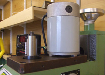
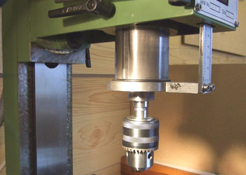
This is a variable speed machine and it uses a small permanent magnet DC motor (3) mounted to the rear of the main head casting. At least I assume it′s a permanent magnet motor as nuts and washers stick to the casing if you let them get too close with the cover off. In front of the motor you can see the nut which retains the captive drawbar and the squared top of the 3/8" Whit drawbar (a bit odd as it is a Metric machine). The drawbar is self-ejecting although the manual tells you to hit with a mallet.
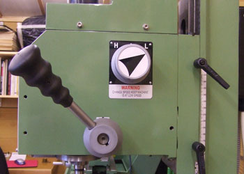
To improve the torque at low speeds the mill has two speed ranges, changeover is simply by turning the knob (4). The low range goes from 0 to about 1100rpm and the high range goes from 0 up to about 2200rpm. The gears are relatively quiet but whine a bit at high speed. So far I have mainly used the low speed range as it copes adequately with all but the very smallest cutters and drills.
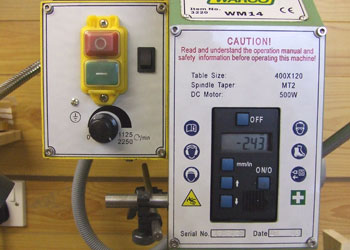
The variable speed control knob is mounted on the front panel of a control box bolted to the left hand side of the head casting. The box houses all the speed control electronics and the NVR start stop buttons (5). The small black switch is an addition of mine to control a low voltage lamp.
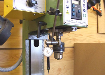
On the front panel of the head proper is a digital depth display (5). The sliding scale of the display is connected to the quill by means of two long allen bolts and a spacer block (6). I noticed that the scale seemed to be grating so I removed the digital display and scale unit. I found that the spacer block was out of square, it appeared to have been filed to length. I squared up both ends by taking a skim in the lathe. On reassembly everything was smooth with no grating. The display part of the scale is clamped in place by four allen grub screws at the bottom of long tapped holes from either side. I utilised one of these holes to fix a short bar which enables a DTI to be clamped in place (7).
The quill itself is quite robust with a stroke of about 50mm. The operating lever on the right has only one handle which means that when drilling sometimes you end up pushing the lever rather than pulling it down. There is a quill clamp on on the left hand side. There is no depth stop on the quill but I found working with the digital display quite easy, only slight problem is forgetting to switch the thing off!
The head can swivel up to 90° either side (8). I have not tried this as when I tested the alignment the head was trammed in at 90° to the table and I will leave it there unless I absolutely have to move it. The head slides on a dovetail column which gives the appearance of being hand scraped, only on the flats though the dovetails are just machined.
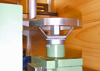
The head is raised and lowered by a feedscrew which runs inside the cast iron column (9). The Z-axis handwheel sits on top of the column and drives the feedscrew directly. This is OK if you are tall enough to reach the top of the column comfortably, it is 1700mm (5′ 7") from the floor and at the rear of the bench. The handwheel has a nicely engraved indexable dial but the index line on the column is somewhat hidden by the motor casing. There are two clamp screws on the right to lock the head in place on the column.
All the slides on the machine have screw adjusted taper gib strips (10) which makes for easy adjustment. When Preparing the machine I removed these and polished them up, as the finish was just as machined, it makes the slides slightly smoother when the gibs are tightened. I thought that all the slides were a little loose for my liking.
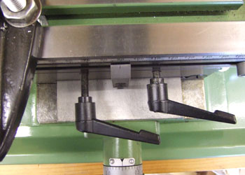
All the slides are fitted with locking screws which tighten onto the gib strips. The gib strips have machined recesses and a small brass pad is fitted between the end of the locking screw and the gib strip. The locking screws have Bristol locking handles so can be turned to avoid collisions. All the screws were overly long and one had been bent in transit. I shortened them all slightly and made one of each pair shorter so that they could overlap one another (11).
When adjusting the gibs and clamping screws I had an interesting problem trying to get one of the brass pads in place behind the clamp screw. Every time I pushed the pad into the hole as it approached the gib strip it would tumble through 90° and disappear. Investigation revealed that the tapped hole for the adjustable gib screw had been drilled way too deep and had intersected the bottom of the clamp screw hole. After a bit of head scratching I overcame this by blanking off the gib adjuster screw hole with a short grub screw screwed in tight and then re-drilling and tapping the clamp screw hole.
The X-axis only has a handwheel on the right hand end of the table (12) unlike the larger models in the series which have handwheels both sides. I haven′t found this to be a problem except for getting showered in hot swarf when taking a hefty cut. I will add a guard to help prevent this, if it works I will put the details in the projects section.
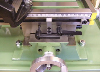
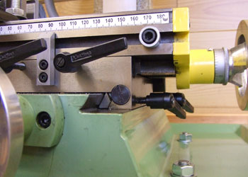
The front of the table is fitted with a mm scale and a pointer which also serves as a stop is fitted to the front of the Y-axis casting. Two sliding stops are fitted to a dovetail slot machined in the front of the table (13). The centre stop is fixed by two allen screws, you would need to be fairly gentle if using the table stops as I think it would be moved out of position quite easily. The Y-axis handwheel is again fitted with a nicely machined indexable dial.
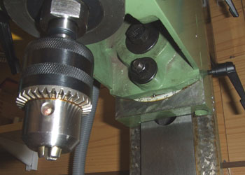
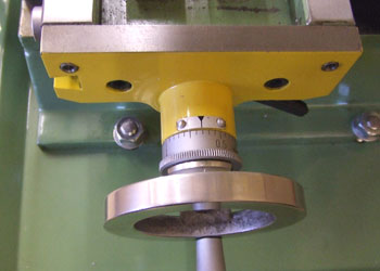
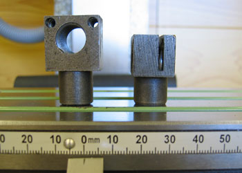
There is a small amount of backlash on all the leadscrews despite these being fitted with adjustable nuts. I say adjustable but they appear to be made from cast iron so I don′t really think they will move much. I noticed that when preparing the machine that one of the nuts on the Y-axis had a slight crack in the adjustable leg. Warco kindly sent me replacements and it is these pictured sitting on the table (14). The smaller nut for the X-axis has very limited clearance beneath the table and the original had been ground down to clear, so much so that the allen screw adjuster had been ground in half! I haven′t yet replaced these nuts as I would like to fit proper anti-backlash nuts but I don′t know if a suitable commercial replacement is available.
I have had this little milling machine for some time and have already made a few modifications to it. I will put the details in the projects section as soon as I can. It is a very nice machine once you get over some of the Chinese engineering that is hidden away. I might, with hindsight, have been better off with the next machine up the range, the WM16, as this has a bigger table, built in speed indicator etc. However I had to start somewhere and for a first machine I am very pleased. I may one day consider the CNC route, I know the larger machines are capeable of conversion, I can see no reason why this one could not be "improved".
Update 2017
The mill specification has now been improved somewhat with a larger table, three handle quill feed complete with a fine feed knob. A rev counter is now standard as is a chuck guard and emergency stop button. There is also a stop built in to re-align the head should you angle it over.
I have been using the machine with a small rotary table and have found that the Z-axis height, or rather the lack of height, can be a bit of a challenge. I think using a standard jobbers drill in a drill chuck to make a circular hole pattern would be impossible unless the rotary table is very low profile. I would say think carefully about getting the next machine up, the WM16, to help aleviate this problem. The WM16 also has a choice of motor and is available with a belt drive now. Out of interest this machine is no longer the smallest in the range, there is also a WM12.