Tachometer For WM14 Mill
Unlike it′s larger brothers the WM14 milling machine does not incorporate a tachometer (RPM readout). Being new to milling and having read that cutters should be run at the appropriate speed I thought some form of readout would be useful as the control knob gives little indication as to the speed set. This I suppose is one of the drawbacks of variable speed machines unless you can measure the spindle speed.
With a bit of internet research I found a reasonably priced circuit board that met my requirements. As is often the case this was not available in the U. K. so I had to order from America. The unit I ordered was a Trexon Tachulator from MKC Tools The unit is available as either a circuit board or a complete boxed unit ready to go. I opted for the circuit board and a fitting kit which contains screws, standoffs and various other useful items. The circuit board comes complete with an optical sensor, detailed instructions and patterns for suitable encoders.
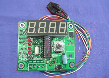
The Tachulator provides an RPM reading and also has facilities to calculate the cutting speed (SFM) for a set diameter which can be entered into the unit. There is a slightly less expensive unit that just does RPM. The circuit board (1) comes ready assembled including the control switch / variable resistor which serves a dual purpose. Press the spindle in to change function and turn the knob to set the diameter of the cutter. A couple of e-mails also established that the unit could use either metric or imperial measurements and an extra 120Ω resistor was supplied loose with instructions where to solder it to the board to enable switching between the two. You can just choose imperial or metric and the resistor will be soldered to the board if required
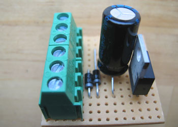
Apart from a case you will also need a small power supply, 9v at about 50mA or you could use a battery. I decided to build my own power supply using an LM7809 on a piece of Veroboard (2). I have included a circuit diagram of the setup I used, I make no promises as to it′s suitability although my version has been working without problems for several months now (3). You could use a standard 9v DC wall wart if you′re not into electronics construction. There is some protection already on the circuit board so the power supply doesn′t have to be too sophisticated. If you would like something a bit more advanced than my effort there are plenty of suitable diagrams on the internet.
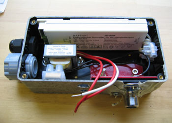
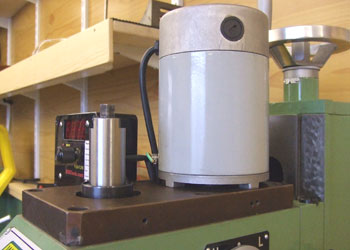
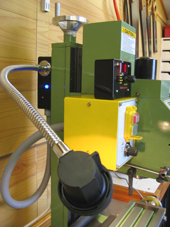
The power supply shown has more than enough capacity for the Tachulator unit in fact the regulator IC will provide up to about 2A. I built the power supply into a separate plastic box that I fitted to the rear of the mill column (4). I also used this box to house the low voltage transformer for a new work light for the mill, that′s the large white unit at the top of the picture. Whilst doing this I also rewired the power supply to the mill. One cable comes from the mains plug through the black gland at top left and is then used to supply the lighting transformer, via a switch on the control panel; the Tachulator power supply and the mill itself. The various cables for the light switch, the mill power and the tachulator power leave the box through the grey gland bottom left and a flexible conduit to the mill control box. The red angle bracket is to support the light fixing you can just see the screwed flange under the masking tape which I am using to stop the box getting scratched.
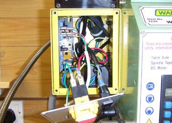
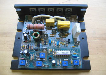
My first idea was to build the tachulator unit into the control box of the mill but there simply wasn′t enough room (5). Nevertheless to achieve what I wanted I still had to remove the box from the mill to make the necessary holes for cabling. I took the opportunity to remove some sharp edges and some weld spatter so that the speed control board and heatsink (6) would bolt up flat against the sheet steel box without any gaps. The speed control board appears well made and is mounted on a substantial heatsink which in turn bolts to the steel case, I have never noticed this getting even slightly warm in use.
The Tachulator board fits easily into a 100mm x 75mm x 40mm ABS box from Maplins (7). The unit comes with a clearly dimensioned drawing to make the cutout and mounting holes in the front panel. The board is Bolted in place using 4 standoffs and a piece of red transparent plastic protects the LED readout. The four wires from the sensor are fitted to a screw terminal block on the circuit board. The power supply is simply plugged in using a 2.5mm power plug into the jack fitted on the board. Because I wanted the unit to switch between metric and imperial I fitted a two pole centre off switch to the rear of the case. One pole of the switch brings the 120Ω resistor into circuit, the other pole of the switch simply breaks the power supply to reset the unit. The unit will not convert from metric readings to imperial or vice versa it simply works in your chosen unit and has to be powered down to make the change. I put the switch at the rear as I didn′t envisage using it often.
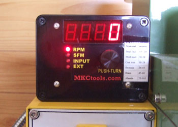
The pre-printed front panel and black anodised aluminium knob finishes the unit off nicely (8). The paper label is something I have stuck on to remind me of the recommended cutting speeds for various materials, not quite so professional!
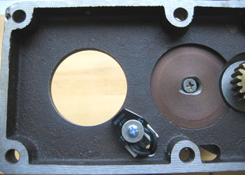
The next job is to fit the sensor and this requires removing the motor and it′s mounting plate (9). There are six cap screws holding the mounting plate in position and to my surprise no means of accurate location, I would have liked to see a couple of dowel pins. Once undone the whole motor assembly can be lifted off carefully pulling the power lead up through the body of the mill. I noticed that there was an earth terminal on the motor but no attached wire, when I reassembled it I added an additional earth wire, you can just see it in the photo.
Once the mounting is removed, the holes for the sensor can be drilled, one for the cable and one tapped to take the M2 mounting screw (10). The sensor sits on a plastic packing piece and I secured it with a little epoxy adhesive to make sure it didn't shake loose. The fitting is a bit hit and miss as the hole in the mounting plate is not concentric with the spindle, it took a couple of goes to get the clearance to the encoder ring set correctly (about 3.5mm). I couldn′t work out a way of measuring this clearance as everything is hidden once the motor is back on, still it works so it must be about right! The sensor mounting method is about as accurate as the Chinese countersink in the photo.
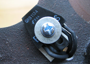
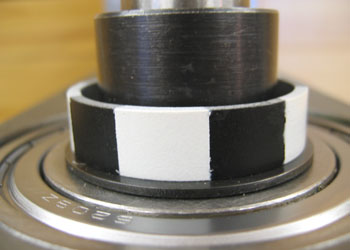
A close up of the sensor shows that it has quite a long mounting slot, so there is plenty of room for adjustment (11), this is before I added the epoxy. The encoder ring I made from a section of plastic drainpipe which was close to the right diameter (12). This ring is a press fit on the main spindle which fortunately extends about 6mm above the bearing housing. The blackened section in the photo is part of the quill and this can also be seen in photo (9) protruding through the motor mounting plate.
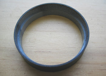
The plastic encoder ring is a section of plastic pipe, with the internal diameter enlarged slightly so that it is a push fit onto the spindle (13). The ring is tall enough to just fit between the top of the spindle and the underside of the motor mount, again this is difficult to measure but a couple of trial runs quickly establishes the correct clearance. I made the ring and painted the segments on it before the Tachulator board arrived. When I read the instructions more carefully I realised that the encoder ring only really needed to have two segments so I re-painted it. The fittings kit supplies a piece of self adhesive aluminium foil to make the encoder but I didn′t fancy the tape coming unstuck once the motor was back in place. Reassembly is straightforward, the trickiest part being threading the wires back through the main mill casing. Without dowel pins getting the correct clearance for the drive gear is a bit hit and miss. I opted to pull the motor assembly firmly towards the front, which would fully engage the gears and then just ease it back a tad (that′s somewhere between a gnats and a smidgen) to provide a slight running clearance.
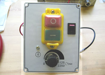
Whilst everything was apart I put a switch for the new work light in the front panel (14). The switch interrupts the mains supply to the lamp transformer rather than switching the 12v lamp supply this means that when not in use the transformer is not powered.
The last job to is to carefully connect all the wiring. Starting with the power supply box, another Maplins ABS box 150mm x 80mm x 50mm, which is bolted to the back of the mill column (15). The main power comes in via the black gland bottom left and into the choc block connector lower right. The supply is then split with permanent feed to the Tachulator transformer via a 1A fuse about a third up on the right and a main feed going straight back out through the flexible conduit to the mill control box, white cable lower right. This chock block also supplies a live out to the light switch, the return from the switch comes back via the same twin core cable, everything is double insulated and earthed where necessary. The return from the light switch goes to the white lighting transformer on the left which also picks up a neutral from the chock block.
The output from the Tachulator power supply is from the green connector block and runs in a twin core cable out through the flexible conduit, bottom right. There is a panel mounted LED with built in resistor which is also powered from the Tachulator power supply, you can′t see the LED in this view, it is hidden by the fuse holder. The output from the lighting transformer runs to a connector block to a twin core cable which can be seen exiting through the red bracket top right and into the gooseneck lamp arm.
Once the power supply box is wired you end up with three cables running down the flexible conduit. One main 240v supply to the mill, one 9v power supply for the Tachulator and one switch wire for the lamp. The flexible conduit exits from the underside of the power supply box and makes a smooth transition to enter the rear of the mill control box where the original power supply entered. Make sure the flexible conduit and the cables inside it are long enough to allow full travel of the mill head.
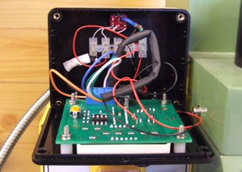
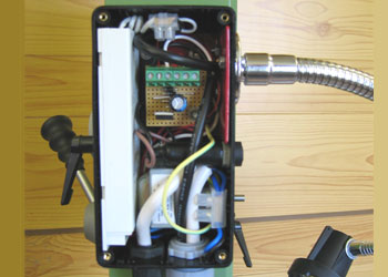
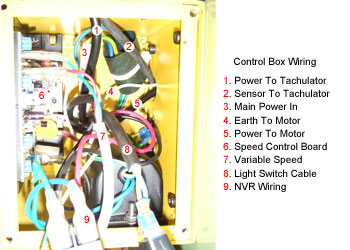
The wiring in the control box (16) is mainly a matter of reconnecting the original cables which have Lucar (push fit) connectors on. There are quite a few of these so it pays either to mark them or to make a drawing so they all go back in the right places. There are three cables from the right hand side coming from the main casing. The motor power which connects back to the speed control board, a new earth wire which is bolted to the main earth distribution point on the right of the cabinet and the four sensor wires in a sheath that pass straight back out through the top of the box to the Tachulator. Three new cables now come into the control box from the rear conduit connection. The first of these is the mains connection which goes to a connector top right wrapped in insulating card. The next is the light switch cable which terminates in two Lucar connectors and is fitted to the new front panel switch. The last cable is the power supply to the Tachulator which passes up and out through the top of the box into the Tachulator housing. The photo (16) shows these cables but it is fairly crowded in there and they are not easy to find.
If you are not happy with mains wiring then this is a probably a project to leave alone. However the Tachulator could be fitted without any of the other wiring just running on batteries or a plug in wall wart taking the wire out through one of the ventilation slots on the rear of the motor casing. The light is a unit I made from a selection of bits and pieces and details are on another page.
Photo (17) shows the finished job with a view of the light, flexible conduit and Tachulator, you can see the LED indicator lamp for the first time.
Flexible Work Light - a simple addition to light the way for lathe or mill.