Mini Projects For The WM250 Lathe
This is a collection of minor mods and additions that I have made to the lathe. No particular original thinking they have mostly featured on another lathe or been seen in a magazine somewhere. I have included a couple of drawings where appropriate but mostly these little bits are self explanatory from the photos. I can recommend the chuck board / tray, very useful.
Chuck Board / Tray
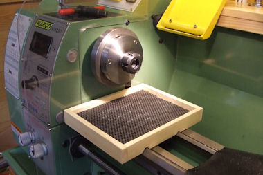
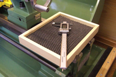
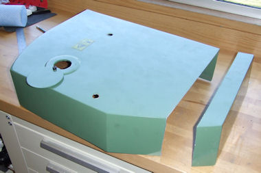
It is always a good idea to put something over the lathe bed when changing chucks. This simple tray has a twofold use, as a chuck board (1) or as a tray to keep spanners, parts, rules or micrometers on (2). Made from a piece of 9mm MDF about 200mm by 150mm with a couple of further strips of the same MDF to let the board stand on the flat parts of the bed. A softwood trim and a coat of varnish add some wear resistance and a piece of rubber drawer liner completes the job.
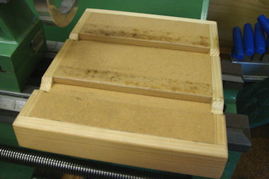
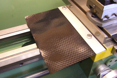
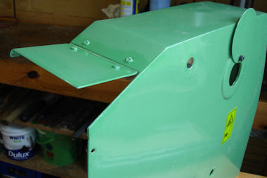
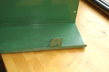
Photo (3) shows the underside of the tray, you can see where it sits on the bed from the oily marks. Photo (4) is nothing to do with the tray but a close up shot of the way protector which is just a length of plastic DPC material sandwiched between two bits of aluminium flat. I have just used a couple of hex head bolts to hold it in place but you could make a couple of knurled head screws. The bolts / screws use the mounting holes in the saddle for the travelling steady and serve the other function of preventing ingress of swarf.
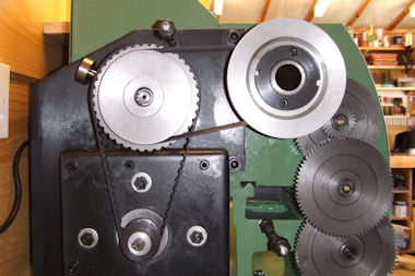
Belt Tension Adjuster
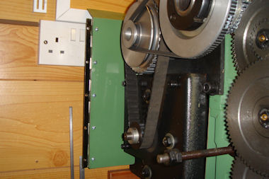
If you have changed the belts from high to low ratios you will have noticed that the tension set screw is cunningly camouflaged by being matt black amongst all the surrounding matt black metalwork and hidden in the shadows behind the intermediate pulley. It is also pointing towards the rear of the lathe so that it can be awkward to get the allen key in there. This simple mod makes belt changing a bit quicker.
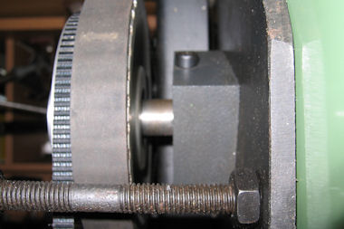

Photo (1) shows the position of the original adjusting screw even with the camera flash on it is difficult to see. I have attached a drawing (2) with the sizes I used it is worth checking that this will fit on your lathe before manufacture (click on the image for a larger version).
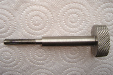
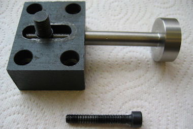
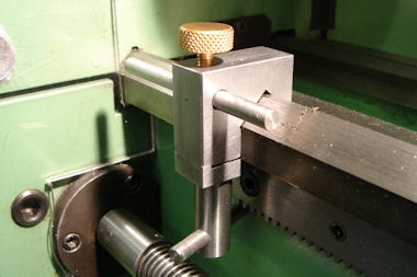
Photo (3) shows the completed tensioner screw. Making this is a straightforward turning operation and the head can be left plain or knurled. Photo (4) shows the screw fitted to the adjuster before I had knurled it, the original screw can be seen in the foreground.
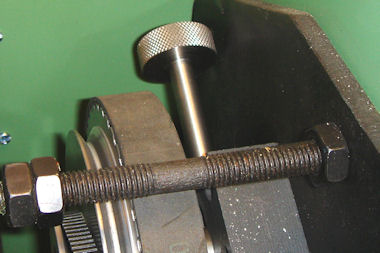
The last two photos (5) and (6) show the adjuster in place. It makes the belt change considerably easier. Make sure it is not too long otherwise it will foul the cover. An alternative to the knurled section on the end would be to make the screw adjuster from 10mm stock and simply cross drill 6mm and Loctite in a short length of bar to make a tee handle (cheaper and not so much turning).
Hinged Change Wheel Cover
My lathe sits in a corner and is tight against the wall and I found that changing speed ratios or change wheels was a bit of a pain. The cover was always getting caught on the back plate or the micro switch and putting it back was just as fiddly Once the cover was removed I usually put it on the floor where I invariably knocked it over. I decided that the cover would be better if hinged so I set to with a hacksaw...
The first thing to do is to remove a section of the cover about 40mm wide, this will act as the fixed portion (1). I have not included any precise dimensions as these should be made to suit your lathe.The cut off section is reversed and fixed to the motor mounting plate. I found that cutting the cover revealed quite a lot of filler and some decidedly dodgy welding but nothing that cant be covered again by a coat of paint.
Next on the agenda is to remove a short section at the rear of the cover to act as a flap to clear the pulley. This flap is reattached using a short length of piano hinge (2). All the cut edges will need a coat of matching paint to prevent rusting. I went to one of the big DIY stores (B&Q) and got them to match some gloss paint for me (the touch up tins that came with the lathe seem to be cellulose based which I don′t like), the swinging cover over the spindle hole is easily detached as a small colour sample.
Photos (3) and (4) show the rear section of the cover fixed in place, I can′t really show a close up photo of this as the gap between the wall and the cover is a bit tight. To fix this in place is a bit of a pain with the lathe up against the wall, you need long thin arms! The way I did it was first to attach the main part of the cover to the fixed section with a strip of piano hinge and M4 nuts and set screws. This can be done on the bench, I clamped the hinge in place and used a power drill to drill through. The cover is thin so it doesn′t take long. Drill mounting holes through the fixed part of the cover (the bit that was the front) and then fit the cover to the lathe using the standard mounting studs and knurled nuts. All being well the cover will be in the right place and what is to be the fixed section will be held against the motor mounting plate. If you have enough space you can drill the mounting holes directly, if you havn′t centre pop with an automatic punch, remove the cover and drill the motor mounting plate for fixing screws. I tapped the plate M4 for 4 fixing screws but you could use nuts and bolts if you can get to the back of the lathe easily.
Once the mounting holes are drilled you will probably need to take the cover and fixed plate apart so that you can get behind the fixed part to screw it to the motor mounting plate. I hope this is making sense, not one of my better descriptions! Try the cover in place to make sure that everything clears. You may find it necessary to remove a corner of the Micro-switch activating bracket (5) so that it clears the corner of the motor mount.
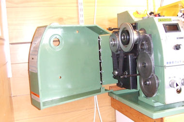
Once finally assembled it should look something like photo (6) you still need to use the mounting studs and knurled nuts to hold the cover in place but I have found it easier than having to completely remove the cover.
Saddle Stop
This is quite a useful little gadget if you need to turn up to a shoulder or need multiple parts the same length. It doesn't really need a detailed write up as it is quite straightforward to make. I have included a dimensioned drawing, usual disclaimer - check to make sure it is the right size for your lathe.
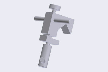
In use the saddle stop hooks over the lathe bed (1) and is clamped to the bed by a screw and flat plate under the bed. All the materials were from stock or the scrap bin, the drawing suggests sizes but nothing is critical. The main body is from a length of 30mm x 15mm bar. I made the clamping screw long enough to make sure that the tommy bar (and your fingers) would miss the rack. The tommy bar is simply a short length of 6mm M.S. round stock, it is a good sliding fit in the clamp screw head. I left it loose but it could be "Loctited" in. The stop bar is also just a length of 6mm round stock in a drilled hole.

Click on the image (3) to get a larger version of the parts drawing. The clamp body is first made into a rectangle by milling the cut ends of the bar straight. Remove the corner on the mill to end up with a squat "L" shape (4A) also mill the step to take the clamp plate. Rotate the "L" upwards to set a 45° angle and mill out the part that fits over the prismatic bed slideway (4B). Drill the three holes and tap as required, de-burr and clean up.
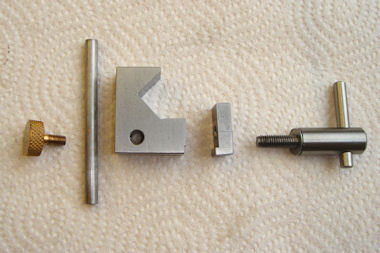
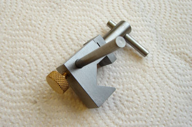
The clamp plate is a small section of M.S. to match the thickness of the main body (15mm), a small step is milled about .5mm deeper than the step in the body so that the plate can pivot to give the clamping force. The critical measurement is the length to ensure that the clamping plate misses the rack. All the parts are shown in photo (5) and assembled ready to go in photo (6).
The turned parts are straightforward, the two 6mm bars just require facing and chamfering. The clamp screw is from a piece of 12mm stock bar turned down to take a 6mm thread for a length of 20mm. The threaded length is 16mm. Once this is done the bar can be parted off to length and the end faced and chamfered.
Saddle Stop - Update 2016
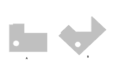
It seems that the "V" angle on the bed is not necessarily 90° so it needs checking before making the clamp. Adjustment can be made with a small file or possibly by using a scraper. The V angle on my lathe is actually 88.4° and the cut-out I made seems to fit quite well, perhaps I was just lucky!
I have given this problem some more thought and come up with a solution. It might not be the best solution but it works! The prismatic bed angle on this and probably other lathes cannot be guaranteed to be 90° neither is it equi-sided. To get the saddle stop to fit correctly either needs very careful measurement and machining or fitting by hand. To try and alleviate this I thought that a point contact approach might work. I came up with what I call "Mickey Mouse ears". This uses a couple of short dowels that stand proud of the surface and avoids trying to match the odd angles of the lathe bed profile. It still requires a certain amount of fitting but this can be easily done in the mill.

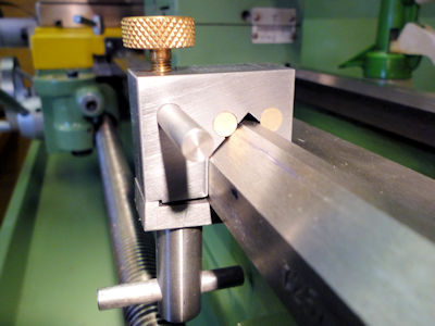
I made another drawing of the body (7) with the dimensions of the "Ears" and making the part is similar to the original but needs two extra holes drilling before the V is machined out. The ears are a couple of 6mm brass dowel pins Loctited into place. I made these over length and trimmed them to length once the adhesive had set. The dimensions I have given make the surface of the dowels about 1mm above the surface of the V cutout. Having made a new body I found that whilst it clamped up tight it could rock to and fro on the bed. To cure this it really needs the vertical face of the body to mate with the vertical face of the bed. This I am afraid is a fitting job as I can′t think of an easy way to measure it. I cured the "rock" on mine by glueing a small piece of aluminium sheet to the vertical face and then carefully machining it back to get a good 3-point contact, i.e. the two dowels and the vertical face. This makes it feel much more secure. If I were to make another I would cut the original "L" shape 1mm shorter and then carefully machine it back after the dowels are in place, bit by bit until a good fit is obtained.
I fitted my revised version near the tailstock to get a photo (8) and you can just about see where I have added the aluminium shim. I have put a few notes on the new drawing which help show what I describe above. I am pleased to report that the modification appears to work and once tightened up is very secure, I couldn′t get it to slide along the bed at all. Once it has been used a few times I am guessing that the brass dowels will bed in and give an even firmer grip.