Maurice's Mods
A couple of modifications for the WM250 lathe from Maurice Duckworth. The first is an improvement to the 4-bolt topslide clamp, the original of which appears at Fitting A Quick change Toolpost To The WM250. The second is a novel and convenient way of eliminating the rattle and clank from the change gears when not in use. There is also a useful method to create neat and professional looking labels which could have many uses in the workshop.
Four Bolt Clamp
The original four bolt clamp plate works well but it is difficult to see the engraved protractor dial (1) as it is at the bottom of a milled pocket. This mod fills in the pocket with a patch plate and puts the numbers where you can see them. Without further ado over to Maurice who provides the photos and description of how to engrave the plate without using a rotary table.

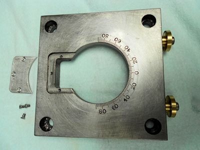
Start by Removing the top slide complete with clamp plate. Remove the clamp plate and reassemble the protractor scale to the top slide and transfer the zero line from scale to side face of top slide. Whilst the clamp plate is unattached, drill and tap the 2 x m5 holes for mounting the two brass stops. Mill a relief for the patch plate see drawing (2) (Click on the image for the full size PDF), to be slightly deeper than patch thickness so that patch is under flush. Make and fit patch to place (I used 6ba csk screws), leave about 3mm excess material i.w.o. bore (to be removed later).
Remove the patch, reassemble the clamp plate with the top slide and install the top slide assembly back onto to cross slide, ensure the clamp plate is square and the top slide is parallel to lathe bed, tighten fasteners, now transfer zero line from the side of the top slide on to the clamp plate top face.
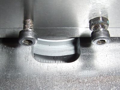
Make and fix to place the 2 brass stop buttons see drawing (2) (Click on the image for the full size PDF) with m5 cap head screws, noting that the small diameter length is made exactly the right length as determined by measuring with a digital depth gauge the distance from the front face of the cross slide to the face of the clamp plate. Once the stops are in place (3) they will prevent the clamp plate from moving when the fasteners are released in order to rotate the top slide.
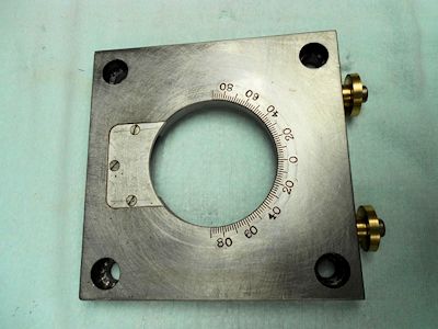
With the patch plate removed set the clamp plate up in the 4 jaw chuck with the bore and face running true. Re- fit the patch plate (4) then skim the patch plate out to original clamp plate bore.
I then measured accurately the diameter of the chuck from this I calculated the circumference length (πD), I then produced, using CAD, a paper band of circumference length divided and marked into 180 equal spaces. The band was then fastened onto the rear diameter of the chuck with Sellotape (each space on the band represents 2 degrees rotation of the chuck). The band will act as a dividing plate.
A single point tool of about 10 degrees angle was put in the lathe tool post but on its side with the top face of the tool facing the operator ensure the tip of the tool is bang on centre. The power to the lathe was disconnected and the drive belt removed to give a smooth rotation of the chuck. The single point tool was moved to the face of the clamp plate at the same time aligning it with the scribed zero line already transferred from the top slide.
With the saddle locked in position and the tool moved via the top slide about 0.1mm nearer the chuck, traverse the tool to the edge of the center bore (zero the cross slide scale). Traverse the tool 5mm towards the operator thus cutting the zero line. If the cut is not deemed deep enough then repeat with a deeper cut. Leave the tool set at the desired depth and NOT retracted.
Now WITHOUT MOVING THE CHUCK use a scribing block with a long fine point to align with any line on the paper band (I stood mine on the flat part below the start / stop buttons and taped it in position) Mark this line as zero on the paper scale I then carefully marked every 5th line either side of zero so that I knew only these lines were 5mm long. DO NOT MOVE THE CHUCK while marking the lines.
Retract the tool, rotate the chuck one division on the paper band and cut the second groove but only 2.5mm long. Repeat this operation a further 3 times. You should now end up with a segment of 1 groove 5mm long and 4 grooves 2.5mm long. Repeat this segment another 8 times . You now have from 0 to 90 degrees in 2 degree divisions on 1 side of the zero line.
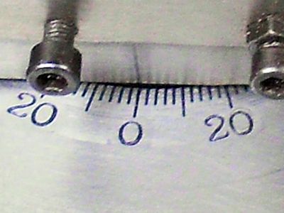
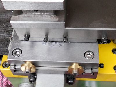
Retract the tool turn the chuck back to the zero line on the paper band now repeat the segment 9 times in the opposite chuck direction. When happy remove from chuck and remove burrs. The degree numbers were carefully punched in using number stamps. The finished result should look like (5) above. The two brass buttons (6) ensure that four bolt clamp plate aligns accurately and repeatably with the cross-slide when the bolts are loosened for adjustment.
Leadscrew Gear Train Retractor
Anyone who has this model lathe knows that the gear train that drives the leadscrew is not the quietest. It is quite easy to disengage the drive but this involves removing the cover and finding an allen key. This modification enables quick disengagement just using one lever.
As supplied the lathe gear train is in constant mesh providing the drive from the headstock gear wheel to the lead screw I have modified my lathe such that the gear train can be taken in or out of mesh as required. When out of mesh this modification results in.
- Reduced wear on the train wheels
- Less load on the motor
- Quieter running
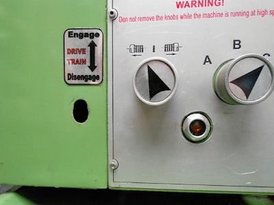
The mechanism is simply operated from a twist and lock knob on the front of the removable casing - up for engage, - down for disengage.
The gear train is mounted on a carrier (quadrant) which incorporates a pinch bolt arrangement (socket head screw), the carrier fits and pivots on the end of the leadscrew. This allows the whole gear train to be moved in and out of mesh with the gear ring on the head stock spindle.
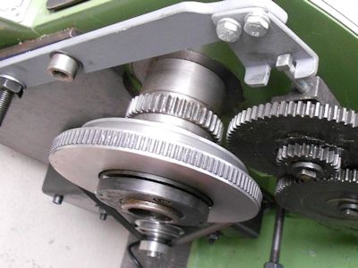
The carrier was removed and a hole drilled and tapped to take a modified, and removable M6 bolt (the head of bolt is 7mm A/F square) this gives the necessary removable clearance (7)
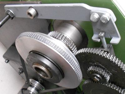
A 1 x ¼ inch mild steel support bar which is suitably drilled at one end to suit existing M8 fastener positions. Fitted to the other end of the bar is a piece of 1/8 thick M.S. angle (8) which has been fashioned to act as a stop for the M6 bolt on top of the carrier. The mounting holes in the angle stop were elongated, it was positioned and secured to the support bar with M6 fasteners such that when the train swings out it stops with about 6mm clearance gap and when it swings in it hits the stop and gives EXACTLY the right amount of backlash with the headstock gear. I did this by setting the mesh EXACTLY, locking the carrier then positioning and securing the angle stop. Then check the swing movement THEN check again to make sure it repeats the correct meshing depth.

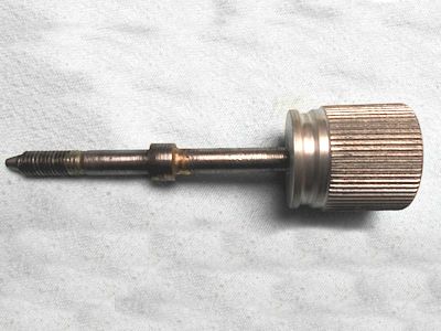
The original pinch bolt in the carrier is substituted with the one in the attached drawing (9) (Click on the image for the full size pdf). The finished pinchbolt screw is shown at (10).
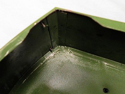
This in turn fits though a vertical slot cut in the front of the removable casing (11). The casing cover has had its top right hand inner flange relieved (12) to clear the support bar.
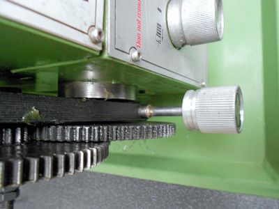
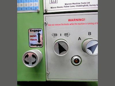
Photo (13) shows the pinchbolt fitted to the quadrant arm and photo (14) the final assembly with the gear cover in place.
The 2 labels were produced on M S Publisher, the image reversed, then printed on to the rough side of overhead slide projector film. The film was cut out and stuck to some very thin flat aluminium plate/foil with clear double sided tape. More double sided tape was used to fix the labels to final position. I moved an existing warning label further up the casing to create space.
If the gear train has been disengaged check when re-engaging to make sure it engages FULLY as it is possible for the two gear wheels to ride on their tips, you will know when the mesh is right because you will feel it and hear it. ALL movements of the gear train are carried out with the lathe stopped. In order to remove the casing cover the new pinch bolt has to be removed. If setting up for screw cutting remove the M6 bolt in top of carrier IF the top meshing wheel is a different number of teeth.
To avoid having to remove the pinchbolt the hole in the cover could be made into a slot by extending it to the right. This might not though be so aesthetically pleasing. To offset this somewhat, a small painted angle plate could be fitted to the headstock to disguise the slot.
My thanks to Maurice for taking the time and trouble to produce the photos and text and for allowing me to share it on Journeyman's Workshop.
Update January 2016
Well it is good to know that others have found this modification useful, a great demo video of the completed gear silencer from George Barczi. Looks as though George has included the slot to allow the cover to be removed easily.
I hope George doesn't mind me linking to his video, it very nicely demonstrates the gear silencing mod. I must admit though that this is not something I have done on my lathe.