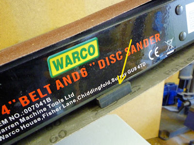
Warco BDS 460 Belt & Disc Sander
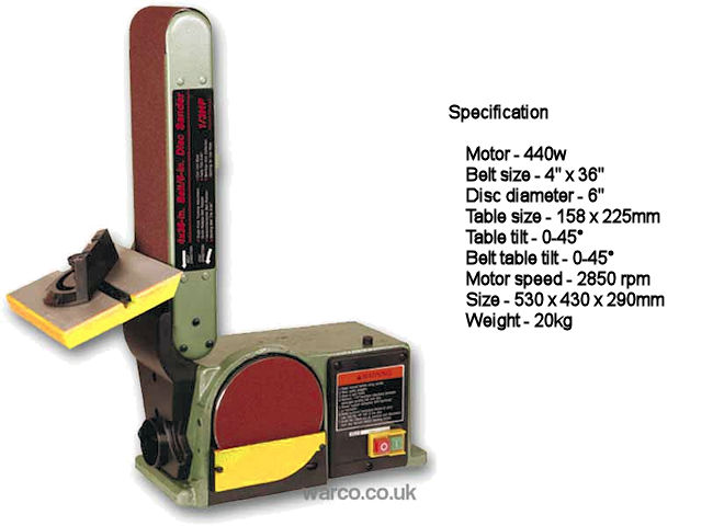
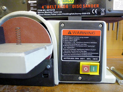
Whilst visiting the Midlands Model Engineering Exhibition I bought a small belt sander which was on offer on Warco′s stand. The unit in question is a BDS 460 Belt & Disc Sander, the unit has a 4" x 36" belt and a 6" disc. Odd that belts and discs are still in imperial whilst the rest of the dimensions are given in metric. It weighs in at some 20kg so I was glad that Warco had a sack barrow available to get it to the car. The catalogue picture and specification are shown below (1). The machine comes complete with an adjustable table for the disc, which can also be fitted for use with the belt when the belt is in the vertical position and a separate table for use lengthwise with the belt horizontal. Apart from attaching the tables and fitting a disc the machine is ready to go, possibly!
I have taken a few photos of the sander as it came and detailed a few quick mods that I made during it's first inspection. The initial impression is that it could be quite a useful machine for the workshop but could have done with a little more care at the assembly stage. It has a sticker on it saying it was checked but my version of 'checking' and whoever checked this are not quite the same! As delivered the machine comes with one coarse belt (60 grit) and a medium disc (80 grit) Spares are available for both belts and discs in 60, 80 and 120 grit, I will order some 120 grit belts and discs which are probably better suited to metalwork.
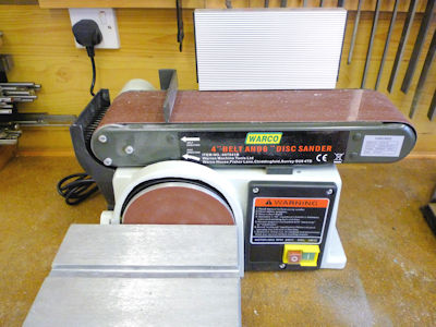
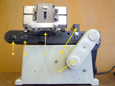
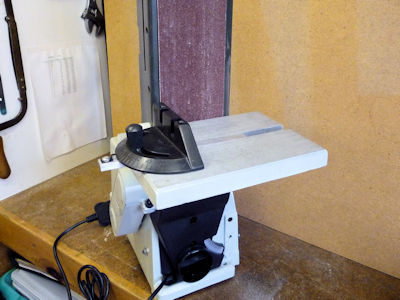
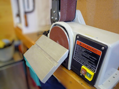
The main body of the sander is made of cast iron which imparts a good deal of weight to the machine, it is definitely not designed to be portable. The belt platen and mechanism is pressed steel about 3mm thick and the rollers and disc are aluminium. As can be seen from photo (2) of the sander the colour scheme has changed from the usual Warco green to a two-tone grey. The photo shows both the supplied tables fitted, one for the disc and one for the belt. The disc table is cast (appears to be zamak) and machined with a slot to take a sliding protractor guide made of plastic. The view of the back (3), not often seen in brochures, shows from left to right; (a) the tracking control knob; (b) the belt tension lever; (c) the table mounting arrangement; (d) the backstop and (e) the drive belt cover. The table for the belt is an aluminium extrusion fitted to an adjustable cast (zamak again) bracket. The table and bracket assembly are adjustable across the width of the belt by sliding on two 10mm rods bolted to the side of the belt platen.
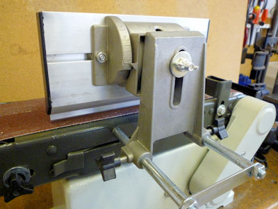
The belt table (4) can also be adjusted at an angle to the belt, useful for sanding a mitre joint. The table and bracket is sturdy but not entirely rigid due to flex where the slide rods are fitted to the side of the belt platen. It would be better if the rods went right through and bolted to both sides which in turn would impart more rigidity to the belt platen. It probably wouldn′t be too difficult to retro-fit some new rods.
The table is fitted with adjustable angle stops (5) but the lack of rigidity might make the use of these somewhat unpredictable I would think, although I haven′t tried it out. Likewise I haven′t checked the accuracy of the angle scale markings either.
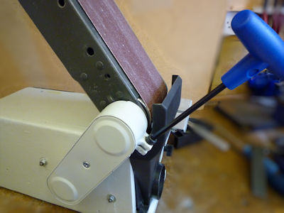
To move the belt from horizontal to vertical just requires loosening one allen cap screw (6) and the whole assembly can be pivoted upwards. This also needs to be done to replace a belt. This photo also shows the dust catching shroud at the end of the belt which channels sawdust down to the 60mm diameter outlet which can be connected to the shop-vac or piped into an extraction system. I did a quick test on a bit of scrap wood and it definitely produces dust a a rapid rate so for woodwork the extract is likely to be a necessity. I haven′t worked out a connection to the shop-vac yet as the hose is only about 40mm diameter. The dust collection from the disc is also ducted to the same outlet.
Once the belt is vertical the other table, which is normally used with the disc, can be fitted (7). This involves removing the backstop as the table uses the same mounting hole. The table is only bolted to one side of the belt platten and this means there is some flex if you press down on the table. This table is a casting and has a slot to take a sliding protractor / fence. The protractor is fited onto a length of aluminium 'U' extrusion which slides in the slot machined in the table. There is quite a lot of free play in this arrangement but it should get to within a couple of degrees. It is possible to fit both tables to the belt platen at the same time, this may be useful in some circumstances although I am not sure for what.
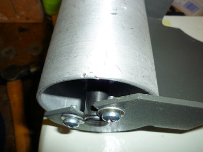
To remove the belt the platen has to be in the raised position so that the belt will clear the support foot and the top of the disc housing (8). The belt tension lever has to be released and the belt can then be slid off towards the front. The belt platen and roller assembly is only secured at the rear left corner where it rotates about the belt guard / support.
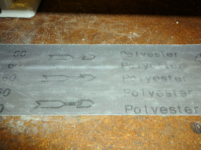
Replacing the belt is straightforward the only thing to note is the direction of rotation which is marked on the inside of the belt (9). Apparently the belt join can come apart if the belt is fitted the wrong way round.
Once the belt is off the construction of the platen can be seen (10), a steel pressing with a couple of reinforcing cross pieces riveted in. I did note that the pressing process has left the top of the platen bowed upwards slightly, probably about 0.5mm higher in the middle. Having never used a belt sander before I don′t know if this upwards bow is a problem, if you were sanding a wide item it would be slightly concave. Despite being a fairly hefty pressing the platen still has a certain amount of torsional flex but I doubt if this would be apparent in use.
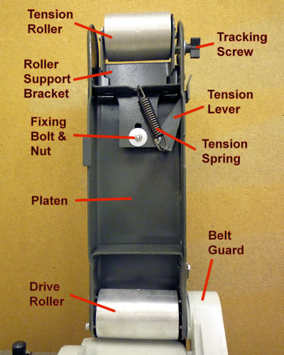
The tension roller at the right hand end of the platen both applies tension to the belt and adjusts the belt tracking. The mechanism is quite simple and a clever design but could be better made. The roller, made from aluminium, I thought might be slightly convex which would help to keep the belt in place but it isn′t (the drive roller does appear to have a slight camber though). The roller has ball bearings quite deeply inset from the ends and a 10mm support shaft, the shaft is machined with a flat on one end to stop it spinning. The shaft is mounted in a 'U' shaped bracket which in turn is restrained in a slot on the underside of the platen (11). The whole bracket and roller assembly can slide both along the table and to a lesser extent from side to side.
In use this bracket is forced out by a fairly hefty spring to provide the belt tension. The operating lever is an over centre design which is either completely loose to change the belt or in tension when in use. The roller bracket pivots and slides about a short column fitted to the underside of the platen with a bolt that goes through the platen and is held in place by a nut and washer. The washer in the photo is one I have fitted. A screw adjuster pushes the bracket from side to side and a compression spring holds it in place this serves to adjust the belt tracking.
Note that the roller assembly is closer to one side, there is about 10mm at the rear and 15mm at the front, this I believe is the cause on a number of problems I encountered before getting the unit to run.
Problems and Modifications
I encountered a few problems with the machine but these were easily rectified and I soon had the sander up and running smoothly. Before running the sander I pushed the belt round by hand, this caused some very strange rubbing grinding noises from within, I removed the belt and made further investigation.
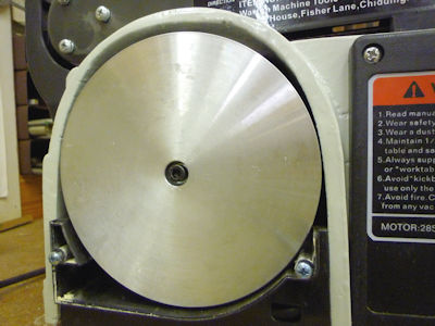
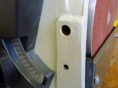
The first thing I found was a a small moulding flash on the plastic housing round the disc. As can be seen in photo (12) the disc is pretty close to the right hand side of both the casting and the plastic moulding. Just above the screw the plastic was rubbing on the disc. I took the disc off and a fine file quickly removed the offending plastic. The disc isn′t exactly central in the casting opening about 1mm at the right and about 10mm at the top. The plastic moulding is actually part of the dust extract ducting, the screws hold a plate over the lower part of the disc.
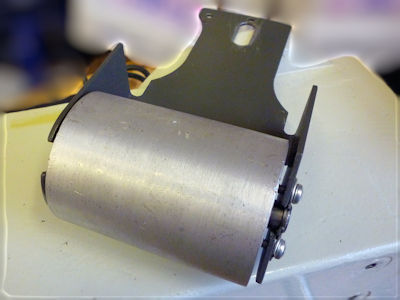
A more serious problem was that the tension roller was rubbing on the 'U' shaped support bracket. I removed the roller and bracket assembly (13) and the first thing I noticed was a hefty dent in the edge of the roller. A further investigation revealed that the bracket was bent, unfortunately I did′t get a photo but basically both legs were pushed over to one side and twisted. The roller and spindle came out of the bracket quite easily. A bit of brute force with the vice, a large hammer and a bit of wood got the bracket back into the shape I thought it ought to be i.e. with the legs at 90° to the base and parallel to one another.
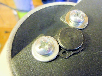
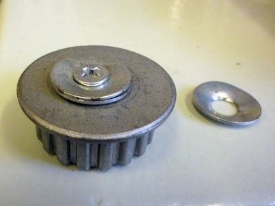
With the bracket straightened out I refitted the roller and spindle (14). This has got to be the most peculiar bit of engineering! Each end of the spindle has a circlip fitted which prevents any lateral movement of the spindle. To prevent the spindle falling out of the bracket slot two screws and washers (15) clamp the circlip to the bracket - weird. You may have noticed that the washers appear to be a bit worse for wear, that′s because nearly every washer on this machine is bent and twisted but some of these were originally trapped part under the circlip and part over - don′t ask me how they managed to do this.
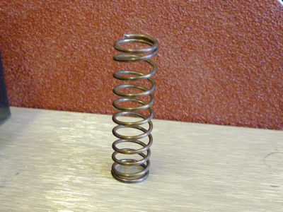
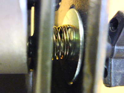
I refitted the roller and bracket assembly and had considerable difficulty getting the spring (16) in place around the tracking control screw. As can be seen from the photo the spring is fairly long and quite thick (about 35mm long x 12mm diameter). I did eventually get it in place but found that even with the tracking screw tightened right up the roller would not sit at 90° to the table. Basically the spring was too big and fully compressed (about 12mm long) would not let the roller move far enough to the back.
I am guessing here but I think this might have been found either during original assembly or at 'checking' and rather than fix it properly a pry bar or large screwdriver was applied to force the roller assembly into place. Thus accounting for the bent bracket and the hefty ding on the roller.
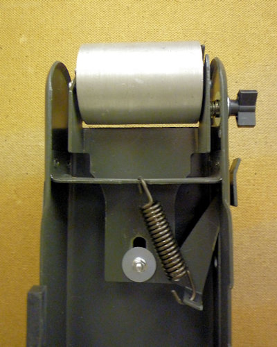
I found a slightly lighter shorter spring and fitted this (17) as can be seen there is still enough space between the spring turns to allow the roller assembly to move into place. I also fitted some new unbent washers!
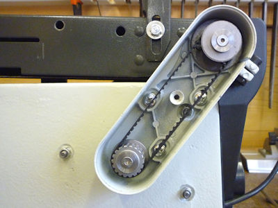
On with the bent washer saga! I took the belt guard cover off just for interest, the toothed belt and pulleys simply transfer the drive at 1:1 from the motor spindle to the belt drive roller. The belt guard also serves as the support for the whole of the belt assembly and is a fairly substantial casting. The belt guard is fitted to the main body by three large pan head screws which pass through slots in the casting allowing it to slide up and down to set the belt tension. The pulleys are a good fit on their shafts which have substantial flats to provide the drive. They are unfortunately held in place by, you guessed it, a bent washer (18) in fact two bent washers.
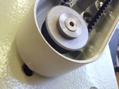
I removed the pulleys, I had to drill one screw out as it had been screwed in so tightly I just couldn′t get it to move before the phillips slot rounded out. I made a couple of 3mm thick washers with a deep countersink and refitted the pulleys with M5 countersunk allen screws (19). The photo also shows a hole just below the belt guard, this apparently is the belt tensioning device. You stick a screwdriver in the hole and lever up against the little nib cast into the cover to slide it up and then tighten the three fixing screws.
The drive pulleys only have a flange on one side so one on the outside and one on the inside to keep the belt in line (20) the pulleys are not interchangeable, the top one has a cast in spacer behind it. The photo also shows the three fixing screws, they look to be behind the belt but this is a photo effect, they are quite accessible. The centre hole is where the cover screws on, you can also see the reinforcing webs on the casting. I think my washers and screws look a bit better than the original!
Photo (21) shows the front plate with the usual safety warnings and the NVR on/off buttons. The plate is not quite straight which causes the lower left corner to ride up on the casting where it is filleted between the front and the disc shroud. I tried to move it but there is no slack in the fixing screws. Not a problem but it just catches your eye. You may also have noticed that the belt platen does not go down into a truly horizontal position, it remains angled up due to the rubber support foot. If you take the rubber off it goes down nearer the horizontal.
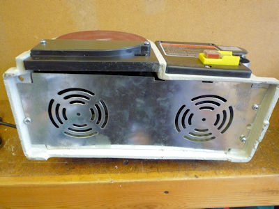
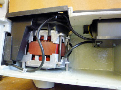
Another view not often seen in brochures is the underside (22), nothing much to see really but at least there is a cover plate with ventilation holes. I unscrewed the plate and noticed that one screw of the three had not been screwed down. It transpired that the threaded hole was full of paint preventing the screw going in, I prodded the dried in paint a bit and managed to remove most of it and then ran a tap through the hole to remove the rest. Photo (23) shows the inside the motor which appears to be an open frame 2-pole induction motor and the back of the NVR switch. The cable is clipped securely in place.
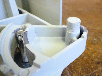
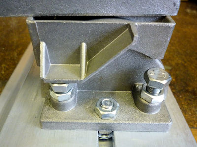
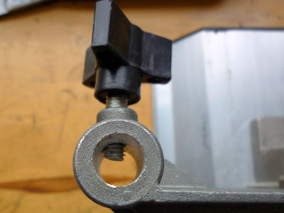
The sanding disc table was reluctant to stay at the set angle this in main was due to the poor fit of the mounting pin in the hole in the casting. The pin on the rear of the cast bracket (24) appears to have been machined, at least it has what look like machining grooves under the paint. The pin however is a very loose fit in the hole in the base casting (25). I found a small piece of brass shim which I cut to length and fitted around the pin. The shim is springy and has lined the hole in the casting where it seems happy to stay without any Loctite or similar adhesive, you can just make it out in the photo. This has improved the rigidity of the table mounting considerably. You can see that the paint is coming off where there are mating surfaces, I think probably a lot more paint will go the same way.
The angle of the disc table to the disc is adjustable. The brochure suggests it will go down to 45° it will but only if the machine is near the edge of the bench (26). Not really a problem as it seems likely to be where the machine will be used. I couldn′t resist putting in the last photo (27) of the belt table bracket, it just demonstrates the lack of care or time used in the manufacture. It would only have taken a little bit extra time or a decent jig to get the hole drilled and tapped on centre, oh well.
Conclusion
The BDS 460 Belt & Disc sander whilst not built to any degree of precision is probably fit for purpose, I am not sure it is actually worth the catalogue price (£98.00 at present) but if it does what you want there is not much else available for less. Record seem to offer what looks like the same machine for twice the price and there are various similar offering around the £125.00 mark. So value wise this would appear to be a good buy provided you don′t mind a bit of 'tweaking' to get it running. If you can collect it at a show, like I did, you can save a few pounds that you would pay for shipping.