Fitting A Quick Change Toolpost To The WM250 - Part 2
The second part deals with modifications to the cross-slide, the mounting arrangements for both toolposts, including the 4 bolt clamp and the manufacture of items common to both, T-nuts and clamping washers. Some of the processes are identical to those in part 1 so you may need to click back to that page.
Part 1 - QCTP & The Cross-Slide Toolpost
T-nuts, Clamping Washer & Cross-Slide Modification.
Before the toolpost can be used you need some T-nuts to fix it down. These are fairly straightforward to make by either milling from square stock or by turning from bar. I opted to make them from 25mm diameter bar and milling off the flats. The T-slots on the cross-slide are quite small and shallow so a fairly large T helps spread the load. Click on the drawing (1) for a larger readable version.

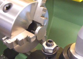
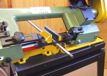
Put the 25mm diameter stock bar in the three jaw, face and turn a spigot 10mm diameter x 4mm long. Centre drill and then drill M6 tapping size. Tap from the tailstock to ensure everything is in line, I only used the taper tap and finished off once I had completed the nuts. Saw off or part off, reverse and hold by the spigot and face to bring the T part of the nut to the correct thickness (2).
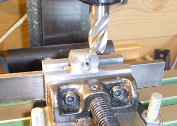
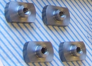
Once the T-nut blanks are complete they need to be brought to the correct width by milling off the edges. I clamped a pair of nuts in the milling vice with the spigots resting on the vice jaws, lowered the cutter until it just made contact and set the Z-axis dial to zero. A quick calculation to work out how much to remove to end up with a 16mm wide flange to the T-nuts (25mm-16mm)/2 gives 4.5mm. I removed this in four cuts as I was a bit worried about how firmly the vice would hold. With one side down to size I flipped the nuts over and pressed them down firmly on a bit of flat stock (3) to make sure that that sides were parallel. Once clamped up the machining process was the same as for the first side. Repeat the process for the other two nuts and the four completed T-nuts can be seen in photo (4).
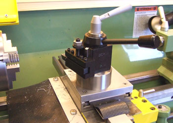
The last item to complete the cross-slide toolpost is the clamping washer. This is 30mm Diameter by about 6mm thick, the thickness needs adjusting to make sure that the clamp handle points to the rear when clamped. I cut a blank about 8mm thick and set this up in the 3 jaw chuck to face one side (5). Turn round and face the 2nd side then drill 8mm for the stud, finish with a small chamfer. The washer in the photo is for the four bolt clamp the finished item can just be seen bottom right beneath the clamp lever in photo (5).
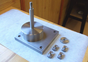
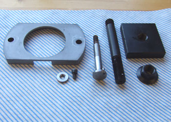
Assembly of the toolpost is straight forward. I screwed the clamp stud in first, just finger tight and then located the four M5 cap screws. I locked two M8 nuts on the stud and screwed this down tight and finished off by tightening up the four fixing screws. I didn′t use any thread locker and so far I have not had any problems with the stud coming loose when unclamping the toolpost. The finished item together with the T-nuts and clamp washer can be seen in photo (6).
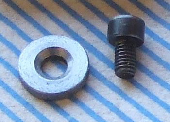
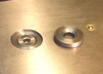
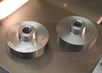
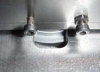
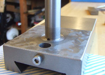
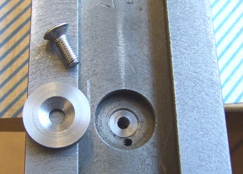
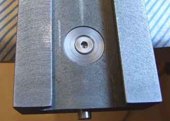
Before I could fix the new toolpost to the lathe there was one minor problem to overcome. The cross-slide leadscrew engages with a nut that is fixed to the underside of the cross-slide casting by a cap screw that goes through the casting from the top (7). As can be seen the original fixing consists of a countersunk washer with a cap screw! This arrangement leaves the cap screw proud of the surface of the cross-slide which interferes with the toolpost mounting. The simple solution would be to replace the cap screw with a countersunk screw. Unfortunately the countersink in the washer is not deep enough for the screw. Rather than try to deepen the countersink in the washer I thought it was easier to make a new washer and this can be seen fitted alongside the old one in photo (8).
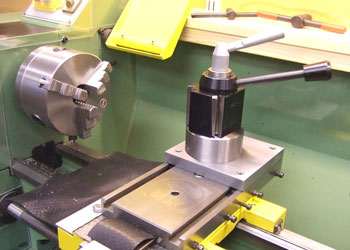
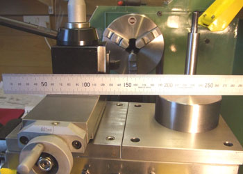
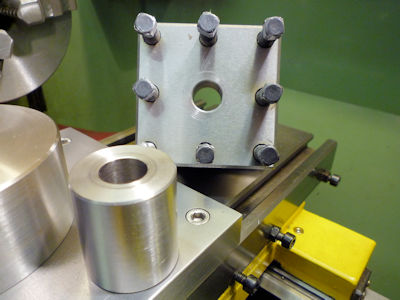
Finally the toolpost can be bolted to the cross-slide (9). The unit is quite versatile as it can be bolted anywhere on the cross-slide, even used as a rear mounted toolpost (10). Additionally the post can be rotated through four positions for added flexibility. In use I have found it to be solid with no vibration, unless you need the top-slide there is no reason why this should not be left on the lathe as the standard toolpost.
The 4 Bolt Clamp
Right, now that I have an alternative toolpost I can get on with fitting the QCTP to the top-slide. First job is to remove the top-slide assembly and reduce it to basic components. Nothing too complicated the only slightly difficult operations are removing the toolpost and the clamp plate. The toolpost stud is a press fit in the top-slide casting and is also located with a pin to stop it spinning, the pin in mine came out with the toolpost. The clamp plate is loose but held captive by the index ring. The index ring is held by four cap screws and two roll pins. Once the screws are out a couple of small wedges between the clamp plate and the top-slide will push the items apart.

I had read an article by Anthony Mount in Engineering In Miniature (June to September 2007), which suggests a replacement top-slide clamp. This seemed to be a good idea as I had already noticed that the existing arrangement left something to be desired. The top-slide is held to the cross-slide table by means of a plate with two clamping nuts. The nuts are hidden under the top-slide and can be a bit awkward to get at with a spanner. It was also evident that the clamping plate was bending when tightened up (11). This design of clamp has been cited as a cause for vibration particularly on some of the 9x20 lathes to which the WM250 would seem to be related. My efforts are based on this article although I have used a thicker plate and a different style of cutout to view the angle dial.
The full size drawing for my version of the 4 bolt clamp is available by clicking on image (12) above, this also gives dimensions for the new toolpost stud to fit the QCTP.
Also see "Maurice's Mods" where Maurice Duckworth describes a method of engraving the clamp plate to enable doing away with the viewport altogether.
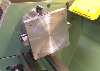
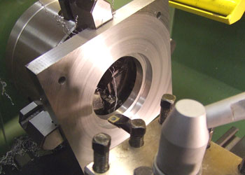
I made the plate from a 5" square of 5/8" bms. Having drilled and counterbored the mounting holes in the mill, as for the cross-slide toolpost. I mounted the plate in the 4-jaw chuck (13) and took a quick skim across the face, This is not critical as the underside of the clamp does not in fact touch the cross-slide. To centre the plate I used the tailstock centre lined up with a centre pop mark I put on the plate while marking out. The longest part of the operation is boring out the stepped recess to take the top-slide index ring. I started with a centre drill and drilled progressively larger holes until I reached ¾" my largest drill. I used several different boring bars until I found one that seemed to work satisfactorily and eventually opened the hole out to 61mm (14). The rebate for the index ring was then opened out to 72mm by 7.25mm deep. I undercut the corner slightly as the index ring has a sharp corner and the tip of the boring bar had a small radius.
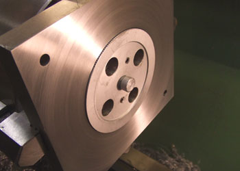
Before I removed the plate from the lathe I tested the fit of the index ring (15). Once satisfied with the fit I removed the plate and set it up on the mill to take out the viewing port. I neglected to take photos of this operation so the best I can offer is a view of the finished article (16). As can be seen the viewing port is fairly small but the numbers and index divisions are quite easy to see, I reasoned that the smaller the cutout the less deformation when the plate is clamped up.
Top-Slide Modification
The top-slide needed some adjustment to allow me to fit the QCTP, the original has a cast in boss 22mm diameter with a 10mm stud which fits the four-way toolpost supplied with the lathe. The new toolpost needs a longer stud 14.3mm diameter and no boss. The hole through the top-slide casting is 10mm this happens to be the tapping size hole for a 12mm thread so I based the modifications around this. I set the casting on the mill and centred the hole and then using a centre to keep the tap vertical cut the 12mm thread right through the boss and the main part of the casting.
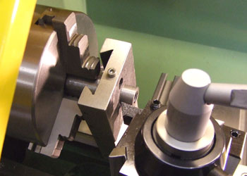
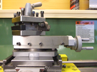
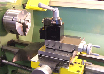
I made a threaded mandrel to hold the top-slide and set this so that the casting tightened against the chuck jaws to ensure the boss was turned square to the slide (17). Being cast iron it only needed to be turned at a slow speed which is good as it was well out of balance. As can be seen there was not a lot of clearance between the casting and the saddle (18).
I was a little worried that the newly machined boss would crack, as at 14.3mm diameter with a 12mm thread down the middle the walls are a little on the thin side for cast iron but it held together even with the stud being a fairly tight fit.
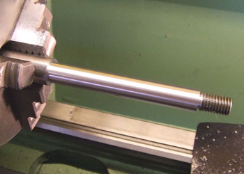
The tool-post stud is from 20mm free-cutting steel held in the 3-jaw chuck and supported with the tailstock centre. A 19.5mm length is reduced to 12mm and threaded to screw into the top-slide casting (19). The stud is reduced to 14.3 mm for it's length and then cut from the stock bar (20). The stud is then reversed in the chuck and a 22mm length reduced to 8mm and threaded to suit the existing clamp handle.
The new toolpost can now be screwed into the top-slide casting. I was pleased with the fit on the finished article, the thread was tight and there was no noticeable step where the stud met the turned down boss (21). Looking from the bottom of the top-slide there is a large machined recess in the casting which took the flat head of the original stud. I decided to utilize this as a means of locking the new stud in place. I turned a large washer to fit the recess and countersunk this to fit a 5mm allen screw (22). I drilled and tapped a 5mm hole in the centre of the stud to take the screw. I reasoned that as the 5mm and 12mm threads had different pitches once tightened up it should prevent the stud unscrewing. So far the stud has remained firmly in place without use of any thread locker adhesive. The washer also fills up the recess and may impart some strength to the top-slide (23).
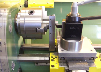
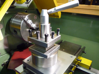
The top-slide can now be reassembled and fitted back on the lathe (25). The new QCTP works well and is very solid. Repeatability is good and it accepts 12mm (½") tooling without problems. One of my original goals was to have both the new cross-slide toolpost and the top-slide at the same height this was achieved as can be seen in photo (24). I now have to think of something to do with the leftover parts (26).
I have included the drawings with the dimensions that I used to suit my lathe. If you are tempted to do something similar please check the dimensions of your own lathe just in case they are different!
Update 2015
Well I thought of something to do with the left over parts, at least one of them. I bored out the old four-way tool holder (27) that came with the lathe to fit the new 14.3mm toolpost. To clamp it down I made a fairly substantial spacer (28) from a piece of scrap bar. I can now use this toolpost as an alternative to the QCTP.