Elmer′s Metric Standby (No.19) Engine
Flywheel
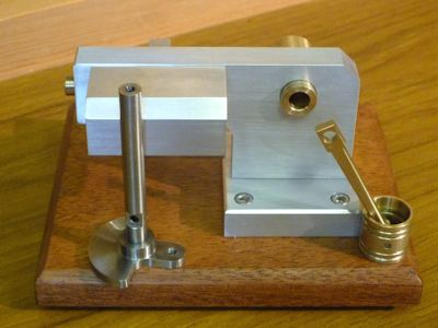
All the static parts of the engine are now complete and the first moving bit I made was the flywheel. This is a very simple brass disc with a relief in both sides as per the original. I used to have great trouble making flywheels like this but I have found a method that seems to work. The single most important thing with a flywheel is to get everything concentric, a wobbly flywheel looks horrible although some of the early steam engines did have distinctly non-round appearance.
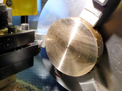
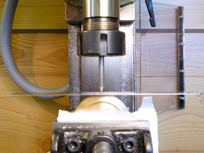
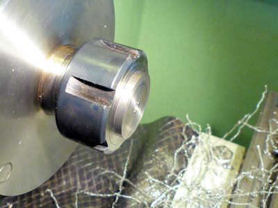
Set the blank in the three-jaw chuck and face one end (39). I took a small cut off the diameter to make sure it was round and measured this diameter as a reference. Using the cross slide dial and the known width of the tool I worked out where to start and stop the recess. I did all this using what I call a trepanning tool although it may have a different name, it is basically a parting tool but used parallel to the lathe bed (40). Once the start position is found simply wind the tool in to the required depth using the top-slide. Withdraw the tool move the cross-slide in the width of the tool and repeat, do this until the inner limit is reached.
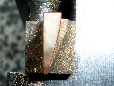
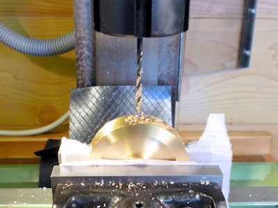
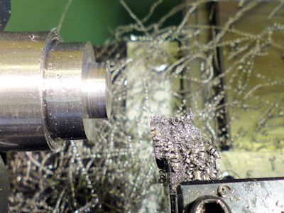
The shape of the tool needs to be something like that shown in (41) my photo wasn′t very clear so I added the coloured line. The edge of the tool nearest to the operator needs enough clearance to miss the outside diameter of the recess. The finish tends to be a bit rough but on the final cut the tool can be wound back the full width of the recess using the cross-slide to leave a reasonable finish and a big pile of swarf (42). You could use abrasive paper to polish the face and recess but beware of the chuck jaws if you have them reversed like mine!
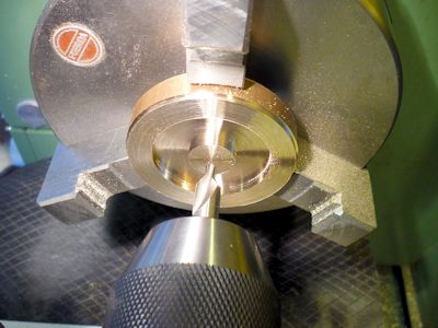
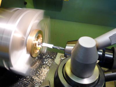
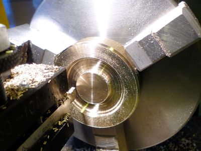
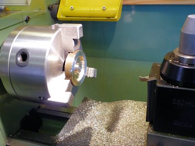
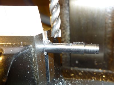
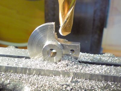
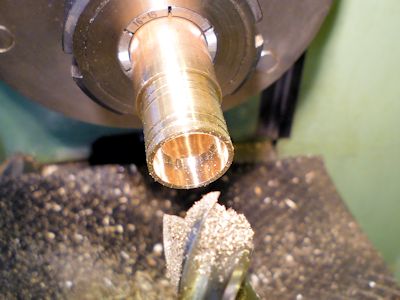
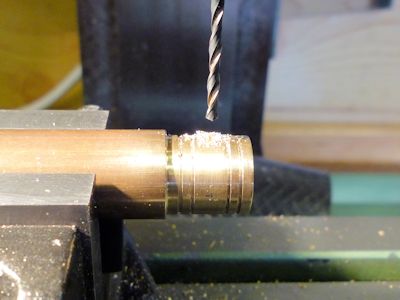
As for the bearing the bore of the flywheel needs to be a good fit on the shaft so the exact method will depend somewhat on what tooling is available. Start by centre drilling to make sure the bore is truly in the middle (43). Then drill through in stages until the final bore size is reached, if available a reamer is probably the best choice for the final stage. I made do with a 15/64" drill (44) as this suited the size of the shaft material I had available.
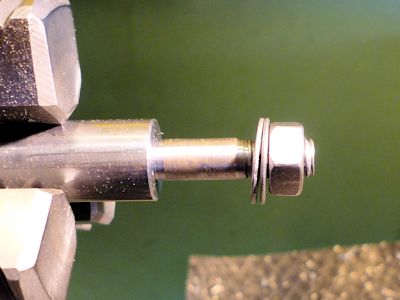
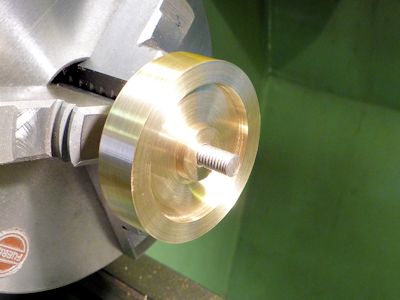
The reverse side of the flywheel and the diameter are best turned on an easily made threaded mandrel to ensure concentricity. The mandrel (45) can be made from any suitable bit from the scrap box but all the turning and threading needs to be carried out without removing it from the chuck. Mount the flywheel on the mandrel, repeat the process for making the second recess and then turn to diameter. The flywheel can be finished with abrasive paper or I find green scouring pads work quite well for a satin finish (46). If you have the luxury of a chuck with soft-jaws these could be used for both sides of the flywheel instead of making a mandrel although the outside diameter still needs turning.
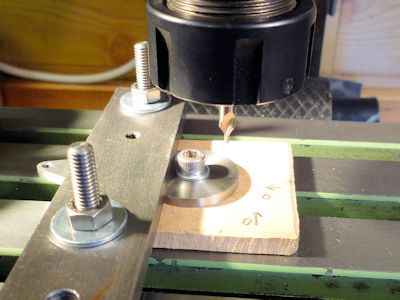
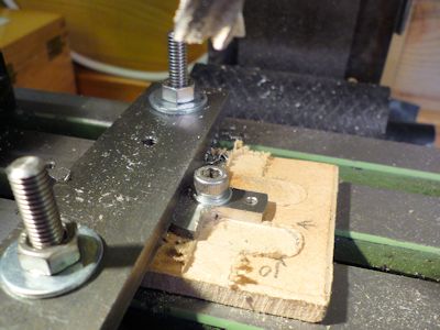
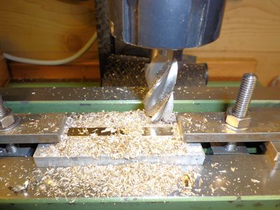
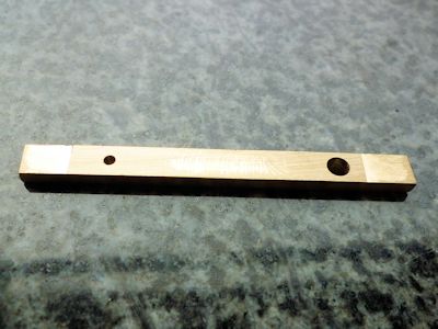
The flywheel needs drilling and tapping M3 for a grub screw that will lock it onto the crankshaft. Using the milling machine finding the centre in the Y direction is straightforward using an edge finder. Finding the centre in the X direction might be more difficult if your edge-finder hasn′t got a long enough tip but can be done using a pointed rod and a straightedge (45) this should get within .01mm without any difficulty. Centre drill and then drill Ø2.5mm, withdraw the drill regularly to clear the swarf. If you can, at least start the tap whilst still in the mill to get a good straight beginning, another tool on my list to make is a sliding chuck held tap holder. It is not possible to tap all the way through the flywheel but down to 8 or 10mm will be plenty depending on the length of grub screw. A small section of brass rod is used as a pad to transfer the pressure from the grub screw to the crankshaft.
Crankshaft Crank & Crankpin
A short length of stainless steel or silver steel (drill rod) is used for this. I found that my stainless steel rod was just under 6mm so I adjusted the hole in the bearing and flywheel to suit, silver steel should be spot on size.
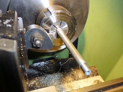
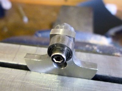
Place the crankshaft blank in the chuck or collet with enough protruding to face and reduce to Ø5mm for a length of 7mm. Without removing from the chuck centre drill and then drill Ø2.5mm to a depth of 16mm for the exhaust port. Extend the blank from the chuck and part off to length (49), face the parted off end if required.
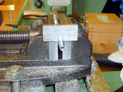
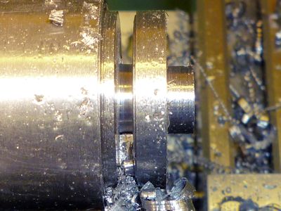
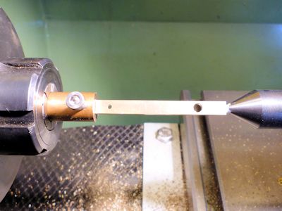
The crankshaft needs two small flats 1mm deep to create the inlet and exhaust ports. Set in the milling vice with enough out to the side to mill the smaller exhaust port. Find the outer end and move the table in the X-axis to centre the mill over the exhaust flat. With a 5mm endmill just touch the top of the crankshaft and then set the depth of cut to 1mm, using the Y-axis cut the flat. Before removing the crankshft drill Ø2.5mm in the centre of the flat to meet the axial hole already drilled in the lathe. The second larger flat needs to be at 180° to the exhaust port to form the inlet transfer port. I expect there is some cunning method to set the exhaust port parallel to the table but the best I could come up with was to hold a short piece of bar againt the flat and "eyeball" it level. The rough method can be seen in (50) but of course you need to hold the straightedge on the underside of the crankshaft.
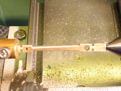
Once happy that the second flat is set at 180° mill 1mm deep (51) but this time 12mm long. Carefully deburr and the crankshaft is ready to go.
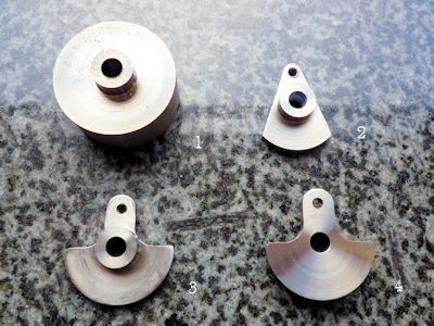
The crank, I have to say, caused me considerable trouble! I ended up having four goes (52), the first time the hole was too big. Then I tried a different shape which was easier to mill but I didn′t think it looked right. The third one I tried to mill with a ball-nose endmill but the burrs were almost impossible to remove and it ended up looking horrible. The fourth try was just about OK but could be improved on.
The turning part of the crank is straightforward, turn the OD down to 28mm and then reduce the boss down to 10mm for a length of 4mm (53). Drill and or ream Ø5mm the hole to suit the crankshaft. Part off to length (54) leaving a little extra to face the outside of the crank. Hold the crank by the boss and face the outside to bring the crank web to 3mm thickness (55).
I tried to mill the crank using a ball nose endmill but wasn′t happy with the finish or the method, I got lots of vibration and huge burrs but a picture if you decide to try this way (56). If you go this route you will need to drill the tapping hole for the crankpin before milling. The hole can then be used to set the crank horizontal using appropriate packing and a rod or drill through the hole.
The method I finally used was to clamp the crank flat onto a small piece of MDF the crank boss sits in a 10mm hole. The only minor difficulty is finding the centre as I had a 5mm cap-screw holding the crank down. You could probably get away with just the one clamp and leave the hole free but I like to make sure nothing is going to move. I actually clamped it up and then removed the cap-screw, centred the hole using a short length of Ø5mm rod in the collet and then replaced the cap-screw. Move the table in the X-axis 10mm and drill Ø2.5mm (57) for the crankpin, tap M3 whilst still in the mill if you can or at least start the thread.
Milling away the cutouts is a bit of an exercise in arithmetic to work out how many turns of the handles are needed to get the 10mm cutter in the right place. I set the mill stops for this to ensure that the cutouts were the same on both sides. I am always fairly cautious with the mill and take light cuts, I removed half the thickness at a time so it took two goes on each side to remove all the waste (58) the pattern left on the MDF shows how the cutter (table) moves. I went in along the X-axis to the stop (moving the table to the right) and then out on the Y-axis to clear the crank. I got much better results this way than with the ball-end milling cutter.
To finish the crank drill the grub screw hole in the boss and tap M3. To make the radius on the end of the crank I used filing buttons (59) cut from a length of silver steel about 3mm thick. They are better hardened but being lazy I left these soft they work almost as well but not if you want to use them again. You could use a rotary table on the mill but it is a long set-up for a couple of minutes work. Clean up de-burr and that should be it for the crank.
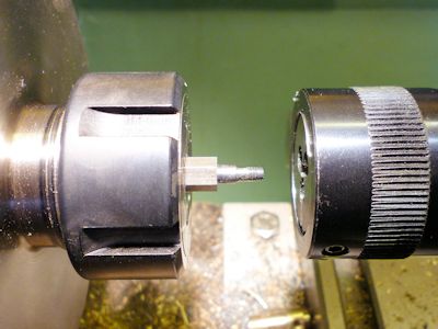
I found a length of ¼"AF hexagonal mild steel rod which I used to make the crankpin but it could equally well be round stock with a slot cut in as per Elmer′s original. Hex bar seems to centre quite nicely in a collet so I used that, a three jaw would work as well. Turn Ø4mm to the shoulder, use a knife tool to keep the corner sharp. Then turn down again to Ø3mm (technically it should be Ø2.98mm) for the thread leaving the 4mm section 3.5mm long. The overall length up to the hex head is only 6.5mm but a little longer makes threading easier and then trim to length. Use a tailstock dieholder to thread M3 (60) up to the shoulder. To get the last thread right up to the shoulder reverse the die so that the side without the lead-in is towards the headstock. Part off the crankpin and hold the 4mm section in the collet to put a small chamfer on the outer edge, fettle as required for the finished item.
Piston & Con-Rod
The piston is turned from brass to be a good fit in the cylinder bore. Be careful when testing the fit to make sure everything is clean otherwise a small bit of brass swarf can wedge the piston in the cylinder quite firmly.
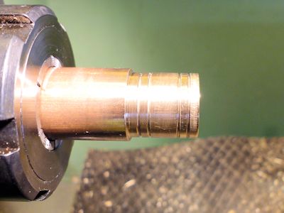
Turn the piston outer diameter nominally Ø14mm but more importantly to be a close fit in the cylinder. Don't try for a good sliding fit at this stage there is too much swarf about. Add the four oil grooves (61) just using a pointed toolbit, a 60° single point threading bit would be ideal. There is no dimension on the drawing but just under ½mm is in the right area stop when it looks right.
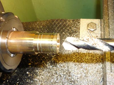
Starting with a centre drill work up to a Ø9mm drill 13mm deep (62) then use a slot drill to make the bottom of the hole flat. Finally open up to Ø12mm to a depth of 5mm using an end mill or slot drill (63). Deburr but don′t part off yet, the next stage is easier using the stock bar to hold onto.
Set the stock bar level in the mill vice and find the centre of the piston. Centre drill and then drill / ream Ø2mm (64) for the wrist pin. I have a very limited selection of reamers so just made do with a drilled hole, I find drilling in small increments usually ends up the right size. Return the stock bar to the lathe and part the piston off to length, skim the piston head for a good finish if necessary.
The wrist pin can be made now and tested for fit in the piston. It could be a gudgeon pin but I think wrist pin is a better descriptive term, I always think of Gudgeon as small freshwater fish! This is just a short length of Ø2mm stainless steel rod. Cut to length and skim the ends and apply a small chamfer in the lathe. You could use silver steel but this is liable to rust if you are going to steam the engine at any stage.
The conrod is from a 3mm thick brass sheet or 3mm x 6mm bar. I found a piece that was about 8mm x 5mm so I had to reduce it′s size to start off. Work from a piece that is some 20mm longer than the finished part so that there is something to hold on to. I first reduced the stock by placing it on a parallel in the mill vice and taking a cut from one edge to smooth it of and then turning it over and reducing to the required 6mm width.
I milled each end to 3mm thick holding it on a parallel in the vice so that I could clamp it down to remove the centre section. I first tried to clamp it down onto a small piece of MDF but found that the clamping pressure was forcing the ends into the wood and the middle was bowing up. I then clamped it onto a short length of aluminium (65) and milled the centre section flat. When clamping make sure that the long edge is parallel to the table so that the two holes can be drilled. Once to thickness find the edge and then the centre and drill / ream the Ø4mm big end bearing hole. Using the X-axis handwheel move the table 38mm and drill / ream the Ø2mm hole for the wrist pin. The conrod is now ready for turning (66), unfortunately I discovered that having only milled one face of my stock bar I had inadvertently stress relieved what was probably an extruded bar and now had a conrod with a distinct upwards bow. I managed to remove the bow by clamping in the vice with suitably placed packing. I now realize that I should have milled both faces to keep the stresses balanced.
You can hold the conrod blank for turning in the four-jaw chuck and in the original article Elmer describes how to set this up. I came up with my own method which uses, for want of a better description, a two-jaw chuck. I measured the diagonal of the conrod blank and it was near enough ¼". I drilled a hole to suit in the end of a stock brass bar and cross drilled and tapped for M4 Two cap screws, voila an instant chuck (67) and the end of the conrod fitted nicely. The outboard end needs supporting by a tailstock centre and I marked and drilled this off the lathe. To mark the centre I used a surface gauge, set the scriber near enough on centre, scribe a line, turn the part over, scribe a line, repeat for the other two edges and you end up with a "#" and then using an automatic centre punch and a magnifying glass it is easy to put a "pop" mark in the centre of the four lines. Use the pillar drill or mill with the smallest centre drill to add the centre.
Once set up in the lathe first turn the whole length to a diameter of 6mm, this is really just taking the corners off. Then turn the small end down to Ø5mm, light cuts are the order of the day here. To turn the centre portion the top-slide needs to be set over. The angle according to my drawing program is 0.88°, I just guessed and set it over a small amount then turned the part down until I could measure each end. The difference should be 1mm and I adjusted the angle as necessary and cut again until the difference in diameter was right. Once the centre section looks right mark the two ends using a parting tool (68) but don′t try to part all the way, it doesn′t work well between centres! Remove from the lathe saw off the waste and file the ends to shape. You could round the ends but I just left mine square and removed the sharp corners.
Assembly & Testing
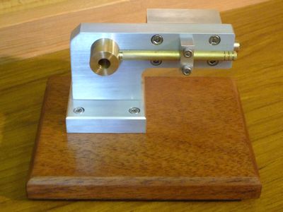
The engine will stand on it′s own foot without overbalancing but I added a small wooden base. I was just going to fix the engine down with woodscrews but decided to return the foot to the mill and counterbore the four mounting holes Ø5.5mm for M3 cap screws.
Before assembly proper the piston needs to be properly fitted to the bore. Clean the piston and cylinder carefully to remove anything that could jam the piston in the bore. I found initially that the piston became quite tight towards the bottom of the bore. I made up a lapping tool with a small piece of brass rod fixed to a threaded rod handle and used this with some fine grinding paste. I applied the paste at the bottom of the bore to avoid as much as possible the open end where the piston was a better fit. I held the lap in the bench vice and just worked the cylinder by hand. Theoretically the lap should be softer than the piece being worked so I should probably have used wood or lead for the lap but it worked OK. I kept testing until I had a reasonable fit the full length of the cylinder. It took longer to clean up between each go than it did to lap and test. Once a good fit was achieved I used a little metal polish to bed the piston and cylinder in.
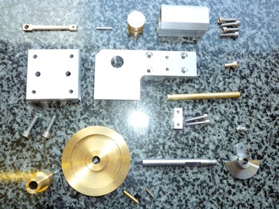
There are 25 parts to fit together if you count the screws (69), if you count the bits in the photo you can only see 24 as the 3mm x 3mm grub screw is already in the crank so I don′t lose it. Fit the foot to the frame with two M4 cap screws. Fit the cylinder to the frame with four M3 cap screws, I didn′t use a gasket for the cylinder but this might be required for use with steam. Fit the inlet pipe bracket to the frame with two 2.5mm cap screws.
The bearing needs to be a good but free fit in frame, do a dry run before using Loctite or similar. Use the inlet pipe to set the bearing in the correct radial alignment, fit the inlet pipe into the counter-drill in the bearing and into the support bracket, twist the bearing until the tube is horizontal and aligned with the frame (70). Once happy with the fit add a little Loctite or similar adhesive (slow setting) to the bearing near the shoulder, apply a little adhesive on the cylinder side of the bearing hole and push the bearing home, align as before and leave to set. The idea is to try and get an airtight seal on both outside edges of the frame but to leave the air passage free. If you overdo the adhesive you may need to run the long 3mm drill down from the end of the frame to clear the hole. Once this is all done the small blanking plug can be fitted to the end of the frame and the inlet pipe can be fitted into the bearing with more of the adhesive.
Two small sub-assemblies next. Fit the conrod, piston and wrist pin together. The original article suggests using a small centre pop to raise a little of the piston metal to stop the pin sliding out. I tried this without success, no matter how I used the centre punch the wrist pin just passed over it despite being a good fit in the hole. I gave up cleaned up the centre pop marks and resorted to more Loctite, just a tiny amount on one end of the wrist pin. The wrist pin should be 0.5mm below the piston surface on both sides. The crank can be fitted to the crankshaft and the position controls whether the engine runs "over" or "under". Over when the top of the flywheel moves towards the cylinder and under when the bottom of the flywheel moves towards the cylinder. The flats on the crankshaft should be parallel to the axis of the crank so that maximum opening is at ½ stroke. If set as in the picture (71) it will rotate "over" and tend to tighten the crankpin. Once happy with the position just clamp up the grub screw.
The piston assembly is lightly lubricated and slid into the cylinder (72) so that the conrod can hang down, don′t forget a drop of oil on the wristpin. The crankshaft can then be lubricated and slid into the bearing and it will just go past the conrod.
Slide the flywheel onto the crankshaft, insert the grub screw pad and grub screw, slide up to the bearing face and tighten the screw. Finally fit the crankpin through the conrod big-end and tighten into the crank (73). If you look closely you can see that I have fitted a thin washer between the crank and the conrod, probably not necessary but it ensures a little bit of clearance. Add a drop of oil to the crankpin and then check that the engine rotates freely, which I am pleased to say mine did first time.
Test run time! I only have a small airbrush compressor so I used this to provide the "oomph". The engine requires very little pressure, I had to unscrew the regulator all the way to get it to run at a sensible speed and there was nothing showing on the pressure gauge. The video (74) shows the engine running quite smoothly but unfortunately you can hear the compressor switching in and out (no reservoir tank).
All in all quite a nice little project and the final result looks good and runs well. Nothing too complicated machining wise and I think the original design stands up to the modifications.