Warco WM 250 Lathe - Review Part 1
Now that the lathe has been in place for a couple of weeks I am beginning to get a feel for it. It is quite different to the old Myford, for one thing it looks much bigger although the overall capacity is about the same. It is difficult to compare the new with the old as the two machines are from different generations the Myford pretty well hand built in the 50′s and the WM 250 more mass produced in 2005. The ML7 was well used and abused when I bought it, albeit for a good price, back in about 1983. I had not modified it or altered it and the only major maintenance was to scrape in and re-shim the white-metal spindle bearings. Some of the finishes were better on the ML7 no rough edges or sharp corners but then again I don′t know what it was like when new! I know for certain that a new Myford would cost three times as much and probably would not make a better job of anything than the WM 250 can do.
Specification
Just so that you can appreciate the size and capacity of the lathe I have included some of the basic details from the catalogue I have added the equivalent details for the old ML7 alongside for comparison:-
- Swing Over Bed - 250mm (10") [ML7 - 180mm or 250mm in gap]
- Distance Between Centres - 550mm (22") [ML7 - 500mm]
- Spindle Taper - MT4 [ML7 - MT2]
- Spindle Bore - 26mm (1") [ML7 - 15mm]
- Speeds - 50 to 2500rpm in two ranges [ML7 - 32 to 640rpm 6 speeds]
- Motor - 750W (1hp) [ML7 - 375W (½hp]
- Overall Dimensions - 1194x610x432mm (47x24x17") [ML7 - 1042x650x520mm]
- Weight - 120kg (264lbs) [ML7 - 86kg]
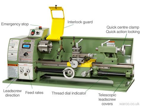
The image above shows the latest model from the Warco catalogue, it has a few minor differences from my 2007 vintage lathe. Leadscrew covers, lever operated tailstock, emergency stop button and a slightly different speed display.
The lathe comes as standard with a three jaw chuck, a four jaw chuck, faceplate, traveling and fixed steadies, two dead centres, four-way toolpost, swarf tray and rear splash guard. Also provided is a toolbox with assorted spanners, allen keys, chuck keys, toolpost key and the change gears that are not fitted.
Headstock
The headstock (1) is basically a box shaped casting that is bolted onto the bed and carries the spindle set in tapered roller bearings. The spindle has an integral backplate which has a 52mm register for mounting the work-holding device. A minor criticism is that the backplate is only about 15mm from the headstock, which can make chuck mounting a little awkward. If you have large fingers trying to hold the chuck in place whilst putting nuts and washers on the three studs can be a bit of a challenge. The studs supplied with the chucks tend to be a little long, not to mention different lengths. I discarded the original nuts and washers and used flanged nuts instead, this makes attaching a chuck slightly easier. I couldn't find smooth faced flange nuts so I made a small threaded mandrel and turned the serrations off to make nice smooth backs. The spindle rotates smoothly with no appreciable runout. Removing the front plate from the headstock reveals very little, apart from the wiring to the display and speed control and the disc with it′s sensor for rpm reading.


Immediately below the headstock is the gearbox (2) which bears the curiously worded reminder to "Don" not to take the knobs off whilst running at high speed! As can be seen the gearbox is oil filled with a filler plug high on the right hand side and a drain plug low on the left behind the belt and gear cover (see Maintenance Oil Change). The gearbox provides tumble reverse and neutral for the leadscrew rotation via the left hand knob. The right hand knob provides three ratios between the change gears and the leadscrew namely A 1:1, B 1:2 and C 2:1. Not really a quick change gearbox but useful for quickly changing feed speeds or you could think of it as providing three leadscrew pitches viz: 3mm (actual pitch), 6mm and 1.5mm.


To the rear of the headstock a sheet metal cabinet contains the electrics, motor and starter panel (3). The starter panel has a NVR stop-start button and a forward-off-reverse switch. There is normally a spring loaded cover with a red stop-lock button over the NVR but I have removed this as I find it annoying having to keep moving it out of the way to use the start button. You need to use the start-stop buttons all the time as there is no clutch on this lathe and the variable speed does not drop to zero rpm. The black lever switch on the right is forward - off - reverse, useful for screw cutting but it should be noted that the motor does not run at full speed in reverse. The main electronic speed control board is situated just below the buttons fixed to the rear of cabinet. The DC motor is at the base of this cabinet and does not get much ventilation, after prolonged use the motor and the speed control board above it have made the lathe quite warm.
The belts and change gears can be seen (4) this is slightly different from earlier models where there was no intermediate pulley. The primary drive is via a toothed belt and the tension on this can be adjusted by loosening the four motor fixing bolts and sliding the motor up or down. The secondary belt is an ordinary V-belt and is tensioned by sliding the pulley assembly left or right. The manual forgets to mention how to release it, (5) two spanner flats on the spindle which unscrew it from a captive t-nut in a slot. Very difficult to see as everything is painted matt black and in the shadows. There is an allen headed bolt which pulls the spindle to the left to apply tension to the belt (see Belt Tension Adjuster). The black disc at the centre of the spindle pulley takes a c-spanner to adjust the bearing preload.


Photo (5) above shows the intermediate pulley arrangement, the rough looking stud holds the cover in place. You can also see on the right a substantial steel plate which serves to hold the various sub assemblies in place. The plate is bolted to the headstock and in turn the electrics cabinet and the motor mounting plate are attached to it. This plate extends about 50mm beyond the rear of the lathe making it wider than necessary if you have limited space for installation. I gave serious consideration to taking a hacksaw or angle grinder to it!
The change gears are mounted on an adjustable arm which pivots about the leadscrew axis (6). I took the arm off to clean it up, you can see from the inset there are some substantial burrs left on it. The gears appear quite well made although if you push them tight together without a working clearance you can detect stiff patches as you turn them probably indicating that some of the holes are not quite concentric with the outer edges. If you follow the manual and put a piece of paper between the wheels when setting up they work quite freely. The wheels do however rattle a bit and if you are not using the automatic feed or screw-cutting, moving the arm away from the main spindle gear makes it much quieter. See Maurice′s Mods Change Gear Silencer for a solution.


The change wheels are held in place by small circular clips which slide over and behind the square heads on the shafts (7). The shafts are threaded on the ends and screw into t-nuts that slide in the support arm. Whilst this works it does not appear very secure as the circlips are free to slide up and off. So far though they have stayed in place. The circlips are not a standard thickness and fit better on one shaft than the other. I may at some stage investigate an alternative method of securing the change wheels. You may have noticed in photo (6) that the end of the support arm is cut away at an angle so that it can be moved closer to the spindle. Whilst I can see the reasoning, I am not convinced that it needed quite so drastic chamfering so that only a couple of millimetres remain holding the two halves of the arm together.
The final photo in this section shows a view of the chuck guard (8). This is switched so that the motor will not start unless the guard is down. It is apparent from the circuit diagram in the manual, that this switch does not work in the same way as the NVR stop button and probably should not be used as a matter of routine to stop the lathe.
Update - 2014/2015/2017
The headstock cover has a plate attached to it outlining the various change gear combinations for screw-cutting and feeds. I discovered an error on mine which hopefully will have been fixed on later models. (See Screw-cutting for more details). I have also discovered that despite the change wheel banjo having the corner removed it is still not possible to use some of the suggested gear set-ups as the banjo hits the spindle before the gears go into mesh! I guess that no-one at the factory ever checked to see if all the proposed change gear set-ups worked but just went with what the calculator said.
The review continues with a more detailed look at the bed, saddle, and top-slide:-